|
|
Post by Warwick on Aug 24, 2008 12:32:29 GMT
Vince, you're forgetting that these cars were built for cruising around on good roads and Rover's overwhelming aim was comfort, smoothness, and silence. The rubber-mounted front-end would have been the determining feature. The rubber coupling will therefore need to compensate for movement at the subframe, and any misalignment.
This has brought back some memories from the mid '80s and my first Range Rover; a 1976 2-door. I'm now puzzled by Rover's ommission of the rubber coupling from these early Rangies. The Rangie's body floats around too. It is mounted to the chassis by rubber mounts but the steering box is bolted to the chassis.
I had forgetten this until now, but the Range Rover had no allowance for this movement and used a steel UJ like the Volvo's. The use of the vehicle off-road resulted in the eventual destruction of the lower steering column bearings due to the constant movement of the rigidly mounted parts.
I remember installing a rubber Metallastic cross-type steering coupling from a Cortina(?) to solve this problem. I think it may have been a Cortina because I think my Bolwell had a Cortina steering column and this was fitted with the same rubber union.
I don't know when this was rectified in production, but typically Range Rover design faults were allowed to persist for years before being fixed. Good ol' BL. I must have a look at my '87 model and my old 1976 parts book (presently on loan to a friend).
Now - the Volvo adapter.
The Volvo's UJ assembly has been cut off just above the lower UJ and it appears that the remaining stub of the interconnecting forged shaft has been inserted into the lower part of the Rover rubber coupling - into the splined section.
The photos will make all this much clearer when I post them in the morning.
|
|
|
|
Post by Warwick on Aug 24, 2008 13:25:23 GMT
I've just heard back from my car's PO.
He didn't do any welding on the plate - There are no studs; only bolts. The 2 bolts with the Nyloc nuts go all the way through. It's beginning to look as though there may be 2 different ZF Volvo boxes that can be used, because judging by your photos and sketches Vince, I can't see how any of the holes could line up.
Unfortunately he can't remember what model Volvo it was, only that he believes it was the last one before they introduced rack and pinion.
Also, the stub of the Volvo UJ shaft is brazed into the Rover coupling.
He also said that other converters usually cut a hole in the inner mudguard to give access to the hydraulic hose banjo connectors, but he found that he only needed to loosen the 4 mounting bolts and the ZF box can move away far enough to enable the banjo bolts to be removed. He felt that this was a neater solution than cutting the body.
|
|
|
|
Post by enigmas on Aug 24, 2008 14:46:29 GMT
"Also, the stub of the Volvo UJ shaft is brazed into the Rover coupling."
Warwick, brazing for this particular mod is not a real good idea. If it were mine, I'd remove the coupling, grind the parts clean, (brazing only adheres to the surface) and MIG or TIG weld the 2 components. You want good penetration.
|
|
|
|
Post by Warwick on Aug 25, 2008 0:45:34 GMT
Warwick, brazing for this particular mod is not a real good idea. If it were mine, I'd remove the coupling, grind the parts clean, (brazing only adheres to the surface) and MIG or TIG weld the 2 components. You want good penetration. I was thinking the same thing, but for a different reason. Brazing isn't just surface adhesion but an alloying of the metals near the surface. If it is done properly, it can be as strong as fusion welding. Its big advantage over welding is that the bulk of the parent metal isn't taken to a temperature that will affect any heat treatment. But the clearance has to be fine. What I was wondering was whether it was overheated and this could weaken the forged uni joint. |
|
|
|
Post by Warwick on Aug 25, 2008 0:48:41 GMT
Here are the photos.   |
|
|
|
Post by enigmas on Aug 25, 2008 10:03:23 GMT
The universal from what I can discern from the images you posted look fine to me Warwick, but the heat required to braze these 2 pieces together is considerable (due to the mass of steel). If brazed correctly the filler rod will flow between the 2 pieces and not just stick to the surface.
From what I can see in the first image a large 'boss' seems to be welded to the uni and then the cross piece welded to this. If the boss was removed (cut off) and the cross piece welded straight onto the uni (using a MIG) there would be greater clearance on the spline of the steering box. It would give you the thickness of the splines exposed in the uni joint.
To check the universal joint turn the steering wheel back and forth with the engine switched off (no assistance) and watch how it works under load. Do this on a bitumen or concrete driveway so that it is loaded to the max.
|
|
|
|
Post by Warwick on Aug 25, 2008 10:49:39 GMT
I'm not in a position to do that yet, but I will be giving it some close scrutiny when I get the chance. I do doubt that the uni is doing anything but acting as the adaptor because the end of the spline is touching the cross and this would prevent the cross from rocking. The deflection visible in the rubber disc also supports this belief.
If tolerances are close then a capillary brazed joint is extremely strong, so long as the parent metal isn't overheated. I'm not that good a welder myself, but having come from that industry I've worked with guys who could weld cast iron to marble using a bamboo filler rod and no flux. (Not much call for it these days).
I'm at a disadvantage in that I have no idea what the original coupling looks like. But until I learn more about this particular job, I do have some degree of confidence because the PO is a retired aircraft maintenance engineer, and not just a backyard mechanic.
|
|
|
|
Post by enigmas on Aug 26, 2008 12:29:07 GMT
Here's a quick update which may be of interest to the few who may want to go this route.
I've drawn up a wooden template which I'll endeavour to profile cut tomorrow morning at work. Two of the Rover holes on the drawings are out of alignment. I was able to position a spare box over the template and correct the alignment. The mounting hole at the column end of the steering box measures 1/2" whereas the other 2 are 7/16".
The template will have 1/8" pilot holes. Two lines will be marked on the plate one horizontal (160mm) and the other vertical (120mm) at the centreline of the boxes.
The template is 12mm thick and this is somewhat irrelevant apart from the fact that if a 1/2" piece of bright plate steel was used as an adapter no machining would be required and both clearance and correct spacing could be accomplished with heavy washers of appropriate thickness cut from 1" steel bar. Initial adjustments would be done with loose washers which would then be removed and measured. The final 'spacer' (made from bar stock) could then be MIGed onto the plate permanently.
I'm using the Rover box and noting the 'fitted pitman arm position' as a reference for locating the holes correctly on the template for the Volvo box.
Once this is done I'll scan the template as a jpeg image and post it on the board. It should then be a simple matter to print the scanned image and check it against the measurements (both vertical and horizontal) and adjust these measurements (use photoshop) until the template is the correct size.
|
|
|
|
Post by Phil Nottingham on Aug 26, 2008 16:30:07 GMT
Well done - may well make this a Sticky when complete so it does not get lost over time
|
|
|
|
Post by Warwick on Aug 27, 2008 1:32:04 GMT
It's interesting how these message boards (forums) work.
Volvo advertisements now appear at the top.
|
|
|
|
Post by enigmas on Aug 27, 2008 8:55:22 GMT
Warwick could you do me a favour and measure the distance from the top of the pitman arm (Volvo box) where it fits onto the splines and the bottom edge of the box where the splines exit. I hope my explanation is clear enough. On the Rover box this is the space where the foam 'doughnut' insert(to absorb the leaking fluid) is fitted.
|
|
|
|
Post by Warwick on Aug 28, 2008 4:53:22 GMT
I can do it on the weekend Vince.
Just to be certain - I take it that you mean the distance from the upper surface of the Pitman arm forging to the lower surface of the steering box casting; at the shaft.
What would be called "clearance" if they were close together.
I actually think that there needs to be something oily or greasy (a wad or a boot) in there to stop water getting into the splines and rusting.
|
|
|
|
Post by johnwp5bcoupe on Aug 28, 2008 6:05:01 GMT
Fit the foam washer/packer as per P5 warwick and pack it with your choice of oil, Copperslip, White Grease or WD40  on the standard box it is usualy fluid from the leaking seal   |
|
|
|
Post by Warwick on Aug 28, 2008 9:07:04 GMT
Thanks John.
Don't tell me you've made a steering box out of stainless steel too.
Do you think it would work if I made a dense foam cylinder with a slit in it so that I can fit it without removing the arm, and I can renew it periodically? Perhaps using an outer split sleeve and cable ties to hold it in place?
You can see how much spline is exposed to road-spray on mine.
|
|
|
|
Post by johnwp5bcoupe on Aug 28, 2008 15:29:28 GMT
Two bits of hard foam and a zip fastener should work Warwick or good old Denso Tape  |
|
|
|
Post by Warwick on Aug 31, 2008 5:55:34 GMT
That sounds like the go John.
Vince,
The "clearance" between the drop arm and the bottom of the box is 15mm.
|
|
|
|
Post by enigmas on Aug 31, 2008 6:52:22 GMT
Note:
This thread has been recently updated to restore the images.
The templates were for research only. Do not use them as the basis for an actual mount. Thanks Warwick. Well, almost there. To use the image below as a reference, print it out, measure and adjust the cross dimensions until they correspond. Maintain proportions precisely (use Photoshop or some similar tool). When the measurements match the line lengths precisely the template should be correct. Glue it to a piece of 12mm MDF (use spray adhesive). Drill holes with a small (pilot) drill (1/16"). Cut out the template with a band saw. Place (and glue the template on your piece of steel (1/2" thick min, 'bright steel') and drill through the pilot holes with a 1/16" drill bit. Trace the outline and cut the shape with a slitting disc in an angle grinder or whatever is easiest. 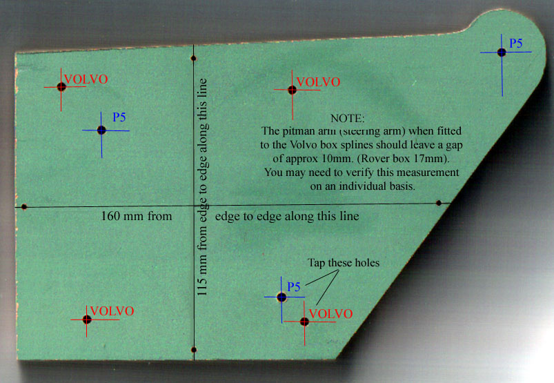 Final Note: Final Note:The RH side of this template may still need to be altered as there is a pivot support for the front leaf springs boxed to the subframe here. This is not altogether clear to me at this time without a stripped subframe to look at. The Rover box is on a considerable angle though, so any 'cutout' may be quite minimal (perhaps nil with a bit of luck). Holes for fixing the box remain unchanged. The first paper template held in place will illustrate any profile changes needed.If anyone has a subframe laying about to check the template against this would simplify matters and enable me to adjust the profile...or just send me a picture of the P5 steering box mounting holes as viewed from the PS front wheel 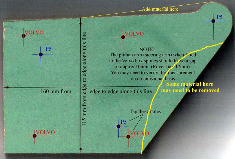 * Please note this template is purely for research purposes.
|
|
|
|
Post by enigmas on Sept 10, 2008 15:06:34 GMT
Thanks for this subframe image Eric. 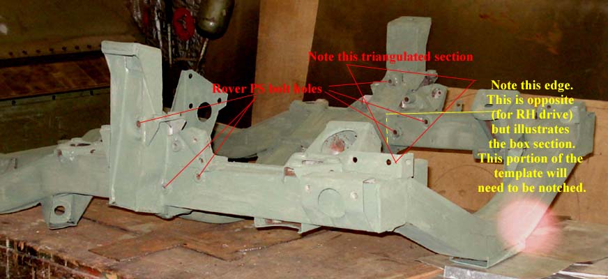 |
|
|
|
Post by Warwick on Sept 13, 2008 0:03:25 GMT
Vince,
Gianni has his engine and steering box out at the moment. The new engine doesn't go in for about a week. Standby for some photos of the steering box mounting point taken square on from inside the engine bay. Should have them by next weekend.
He's also just finished developing a kit to fit massive (and cheap) AU Falcon callipers and DBA ventilated racing rotors (not so cheap) to the car with no modification. Just bolt on. He was showing me the photos last night.
|
|
|
|
Post by enigmas on Sept 14, 2008 11:18:10 GMT
I'm numb Warwick! The racing rotors though beautifully constructed and adjustable in many ways may be too prohibitive for most re: cost factor. Still a job well done. Looking forward to the pix. (As an aside, I'm still aware that I've got to measure my LPG tank for you...cough, cough...a bit under the weather of late.)
|
|
|
|
Post by Warwick on Sept 15, 2008 0:07:54 GMT
Plenty of time Vince. Whenever you get a chance.
I'm off to do my annual circuit of the state for work, so I'm away all week. Next weekend will be taken up planting 800 plants along our river boundary as part of a Melbourne Water willow removal program. So the car is still languishing in the back shed.
I did get a chance to start work on the sliding doors of the main shed so I'm hoping to move the car in there before too long.
The main reason for using the racing rotors was their ease of adaptability. Higher rotor cost offset by lower adaptation cost. Although he was looking for significantly better brakes because the car is his daily driver and the new engine is 5-litres. Speaking of brakes - he made an interesting comment on Friday night. He said that some time back he was on a club trip and lost his rear brakes. To get home, he pinched off the hose to the back axle and the improvement in braking was remarkable. The brake feel and stopping seemed better with all the effort going to the standard front discs. Interesting.
I think I'll suggest to him that he posts his photos on the forum. He is a member but only browses occasionally. By chance we will both be in Bendigo tomorrow night so will be catching up for a drink.
Hope you're feeling better soon.
|
|
|
|
Post by enigmas on Sept 15, 2008 7:22:34 GMT
Considering the P5s are single circuit brakes he's a brave man Warwick. There are street legal braided brake hoses available for cars now and I'm sure this would improve braking efficiency on the P5s if fitted. Both my motorcycles run braided lines and the braking is excellent.
|
|
|
|
Post by Warwick on Sept 15, 2008 10:56:55 GMT
Considering the P5s are single circuit brakes he's a brave man He already has dual circuits using the same Falcon mastercylinder you have, I think. |
|
|
|
Post by Warwick on Sept 29, 2008 23:58:42 GMT
Here are some close-ups of where the Rover steering box bolts on. (Gianni's car). The lower hole has a jemmy stuck in it.   |
|
|
|
Post by enigmas on Oct 5, 2008 11:51:05 GMT
Thanks Warwick for the pix of Gianni's front end but one of the mounts is still obscurred by the the shock-absorber in the first picture. If you look carefully you'll see contact marks on the used mounts and just a heavy coating of road grime and oil on the surface of the other locating dowel ( unused mount).
Note: Take a look at the images of the grey subframe (Eric's) at the top of this page and you'll see this unused mount.
|
|


 on the standard box it is usualy fluid from the leaking seal
