|
|
Post by Warwick on Oct 5, 2008 23:51:20 GMT
Yep, I know Vince. But I thought I might as well post it anyway since they are views from additional directions.
|
|
miguel
Rover Fanatic

Posts: 462
|
Post by miguel on Nov 22, 2008 19:58:15 GMT
Dont know if it was in this thread, but Vince asked me to post pics of the steering bolt holes in the subframe. Only now I removed it, both box and relay. Since my car is a LHD the holes used for the box and relay are simetric, but all holes exist there. Left hand side: 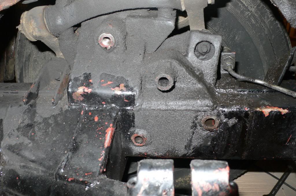 Right hand side: 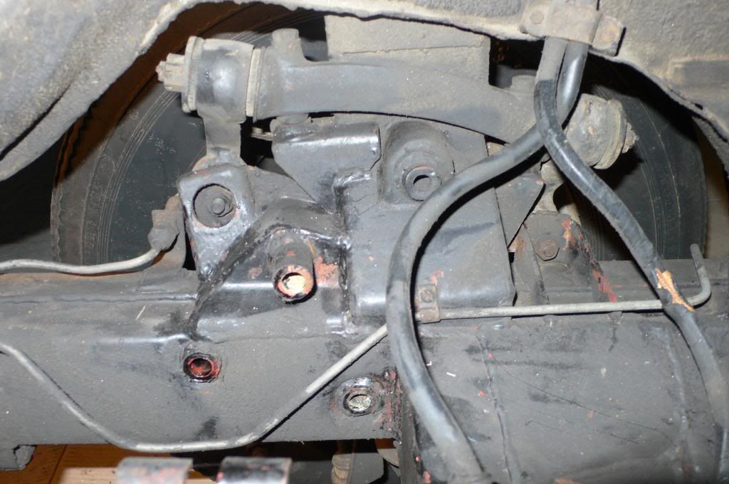 |
|
|
|
Post by enigmas on Nov 23, 2008 2:26:58 GMT
Thanks Miguel, that's exactly what I wanted.
|
|
|
|
Post by Warwick on Feb 23, 2009 5:22:18 GMT
Sorry it's taken so long Vince. I took her out for a run yesterday after checking the filter and fuel pump output. Starts well but something still not quite right. But I'm working on it - albeit very spasmodically. Anyway, since she's mobile again I put her up on the ramps. (My friend's daughter's car is immobilized on his hoist, so couldn't use that). Anyway, the ramps gave me a chance to get some distance between my face and the under side of the steering box. The previous owner was correct when he said he recalled that 2 of the Volvo's mounting holes aligned with 2 of the P5's chassis holes. In the photos below, the 2 Nyloc nuts are on long bolts that come through all the way from 2 of the original steering box chassis holes in the wheel well. The other 2 bolts are screwed into tapped holes in the adaptor plate. The 3rd P5 chassis hole takes a bolt from in the wheel well which screws into another tapped hole in the plate. You can also see where the plate has been scalloped out. Looking at your template, this probably means that the drop-arm isn't in exactly the same place as it was originally. I'm assuming that you arrived at the template layout by working backwards from the ball at the end of the arm when fitted to each box. Anyway, it works perfectly where it is and there are no apparent unusual or unnatural angles in the link rod. The car tracks well, steers precisely and there isn't any sign of tyre scrub. It just has more lock than the original and so you can rub the inside of the rear of the tyre on the chassis rail. This may change when I reduce the tyre diameter.    |
|
|
|
Post by johnwp5bcoupe on Feb 23, 2009 10:35:04 GMT
Looks good Warwick  what no leaks  |
|
|
|
Post by enigmas on Feb 23, 2009 13:36:54 GMT
I'd almost forgotten about this post. Nice to see your pix of the mounting Warwick. Most of my work on this is based upon extrapolation from the steering boxes of both vehicles that I have in my possession. There is an unused hole on the sub frame when the Rover PS is mounted....perhaps it is used for the manual box? This is probably the other mounting hole picked up on your installation? I can't visualize how it is picked up!
According to my figures that bottom nylocked bolt is out approximately 3/8" (needs to be moved back towards the driver 3/8" and lowered 3/8").... but hey it works and I'm doing this on the basis of comparing centre-lines of the rocker-shafts of both boxes without a stripped sub-frame handy.
|
|
|
|
Post by Warwick on Feb 23, 2009 23:35:08 GMT
I'll take the RH wheel off on the weekend and get a square-on shot.
|
|
|
|
Post by Warwick on Aug 15, 2009 11:50:57 GMT
Okay Vince and Paul, so I've been a bit slow. You should know me by now.
What's 6 months anyway?
I took the wheel off again today and checked the bolts on the box and I was definitely right with my assumption earlier.
Vince, would you mind taking another photo of your Volvo steering box, and e-mailing it to me please?
I need a photo taken from the side that bolts against the subframe (the hidden side).
Could you take it square on please.
Lay it on the floor and pack under it if necessary to make it sit with its mounting face upwards, and parallel to the floor. Then take the photo from directly above and orientated as it would be in the car. i.e. with the drop arm roughly at the correct angle.
Perhaps you could take a similar one from the other side too.
I'll then make up a composite photo with arrows and annotations showing what the adapter plate looks like.
It really is very simple and there are no tricky measurements necessary. Very easy to make yourself.
|
|
|
|
Post by Paul - P5B Coupe on Aug 16, 2009 6:09:59 GMT
Thanks Warwick & Vince.
I have passed on Vince's drawing of the adaptor plate to my engineer, as well as copies of the info and pics already posted to this thread. Will await any further information and pass it on to him as and when it is posted here.
Thank you both for your assistance to date. I am looking forward to the day when my P5 has a modern, leak free steering box.
Paul
|
|
|
|
Post by Warwick on Aug 16, 2009 10:21:21 GMT
It's very much simpler than Vince's template, Paul. Don't let him spend too much time on it.
You'll see why when i get Vince's photo.
It's just a thich square plate with 2 holes and 2 studs welded on. Now critical dimensions to achieve alignment. The original box's chassis mounting holes provide the alignment and correct positioning.
|
|
|
|
Post by Warwick on Aug 18, 2009 4:53:20 GMT
Paul,
Vince must be away, or sick. He hasn't been on-line since last Friday - which is unusual.
Are you able to take a photo as I've outlined in detail a few posts above?
|
|
|
|
Post by enigmas on Aug 23, 2009 12:01:59 GMT
I have been away Warwick (Sydney... for a wedding and a mini-disaster' also occured that I'm just now starting to resolve).
Warwick I'll get that photo to you tomorrow evening.
|
|
|
|
Post by Warwick on Aug 23, 2009 12:41:51 GMT
That last post was last Monday Vince, before I learnt of your drama. After I got your e-mail, I didn't want to bother you with relative trivia, so Paul is taking some photos of his today (Sunday). You've got enough on your plate at the moment.
While me on the other hand - I'm just sitting here having a nice cuppa and a glass of port, while the family is away skiing. Such is life.
|
|
|
|
Post by Warwick on Aug 24, 2009 14:03:19 GMT
Okay, I've edited Paul's steering box photo and this is how it all goes together.
I've removed the photo that was inserted here, to correct an error, and reposted it on the next page with the drawing of the plate.
The 2 long bolts that pass right through the chassis rail, the plate and the steering box, are retained by Nyloc nuts in the engine bay. If you look at the last 3 photos in the previous posts you can clearly see the Nyloc nuts.
You can also see the area where the plate has been scalloped out to accommodate the part of the box casting that carries the output shaft.
Earlier photos on previous pages also show the adaptor required to connect the steering shaft to the Volvo input shaft using what I presume to be the Volvo uni-joint and the Rover "Flexor" rubber coupling.
As I've mentioned previously, mine is the only P5 or P5B that I've ever driven, so I have nothing with which to compare it. I've heard of light or vague steering at speed in the V8 but I found that when driving this at speeds of up to 110 kph, the steering was perfectly acceptible despite the narrow, large diameter light truck radials. No wandering or vagueness when running straight ahead.
There is one thing I would do differently, and probably will one day. The high and low pressure hydraulic lines require banjo fittings and are stuck hard against the body. You can see the 2 banjo bolts in the photo above. An earlier photo also shows then when installed. It is necessary to attach them before mounting the box.
I would have 2 short adapter tubes made up to bring the hose connection points to a more accessible location when the box is installed.
|
|
|
|
Post by Paul - P5B Coupe on Aug 25, 2009 7:49:18 GMT
Thanks for your post Warwick. I have taken a copy out to Ian (my engineer). Hopefully he will give me a call soon to say he is ready to fit the steering box - but it is one of those back-burner jobs, so who knows.
Didn't get a chance to look at the rear springs to-day - got allocated other duties by she-who-must-be-obeyed.
|
|
|
|
Post by enigmas on Aug 25, 2009 10:37:39 GMT
Warwick, very good. From your picture above the adaptor plate is parallel with the bottom of the mounting flange on the Volvo box. The 2 red holes (LHS) and 1 green (centre taped) hole attaches the box to the frame. The other 2 green (RHS taped) holes attaches the box to the adaptor. The box is held to the subframe at 3 points. Just quickly knocked this drawing up Warwick. Can you add or provide details to it. (Nothing to scale) Also the bolts: Length, diameter and thread type? Then the adaptor can be fabricated at any engineering shop. 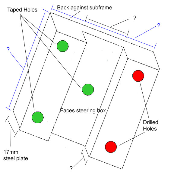 Note: The steering box is used as a template to drill the holes in the adaptor. The taped hole at centre is drilled once the adaptor not the steering box is bolted to the subframe. It is drilled through from the rear with a small drill (say 5/16") and then drilled marginally larger (depending on the diameter of the bolt used and then taped. |
|
|
|
Post by Warwick on Aug 25, 2009 11:20:10 GMT
Correct Vince.
Although on mine, the depression for the steering box "bulge" has been taken out with grinder, rather than being milled out, so it could be made at home with no special equipment.
I can get the dimensions next weekend, although Paul's engineer may have figured it out by then.
The bolts used are the same diameter as the original bolts - or very close. They are a neat fit in the chassis holes.
Any use of a pilot drill to locate the centre hole would need to be done carefully, or by using a suitable tubular guide to ensure that it is centralized.
|
|
|
|
Post by enigmas on Aug 25, 2009 11:42:26 GMT
Warwick, for the centre hole you could use a drill bit that is a tight fit in the mounting point but only drill in about 1/16" or possibly less. This pilot mark/hole could then be drilled with the appropriate drill bit for taping on a small pedestal drill.
|
|
|
|
Post by Warwick on Aug 26, 2009 3:17:32 GMT
CORRECTIONI got the 17mm dimension from the previous owner. We had another tree come down in the storm last night and it flattened a gate to a neighbour's paddock. His cows were eyeing the breach in our defences when I got up this morning, so I had a bit of chainsawing and fence building to do before coming to work. Since I was dirty and wearing old clothes, when I finished I decided to crawl under the Rover and measure the plate. It is actually just over 15mm thick so I suspect it is 5/8" plate. I don't want to remove the bolts at this stage, but the heads are all the same size and they take a 16mm or 5/8" AF ring spanner, so if someone wants to work backwards from that to get the bolt size. I'll update the previous composite photo soon. (By the way Vince, your drawing needs to be rotated in the opposite direction). Paul, if your engineer can provide the locations of the holes when he has finished making the plate, I will add the details to the drawing.  Remember that the drawing above is shown as you would view it from inside the engine bay, whereas the photo below is the view from inside the wheel well.  I've reposted the photo below from an earlier post. It's taken from directly above while leaning over the offside (driver's) wing. It shows the coupling arrangement between the Rover steering shaft and the Volvo box. You can also see one of the banjo unions for the hydraulics, and how close it is to the bodywork. The hoses must be connected to the box before it is bolted to the chassis. This is why I suggest making up some short extension tubes to avoid this. 
|
|
|
|
Post by Warwick on Aug 31, 2009 1:25:16 GMT
Is the mounting face of the Rover box flat? I mean, are the holes through which the bolts emerge from the chassis all in the same plane? I've copied one of Miguel's photos and circled the hole in question. It's impossible for me to tell on my car, with everything in place. Does the extension tube that is welded through the hole stick out further than the side face of the chassis rail, as appears to be the case in the photo, or does it just bring that mounting point out to the same vertical plane as the other holes? This is fairly important. If the tube just extends to the same plane as the other holes, then the mounting plate and Volvo box will mount straight on. However, if it extends beyond this, then it will need to be cut off.  |
|
|
|
Post by Phil Nottingham on Aug 31, 2009 6:52:25 GMT
They are flat ie on the same plane
|
|
|
|
Post by Warwick on Aug 31, 2009 6:56:59 GMT
They are flat ie on the same plane Thanks Phil. I was hoping that was the answer. No problem then. |
|
|
|
Post by Warwick on Feb 3, 2010 6:05:28 GMT
While I have the heads off and visibility is greatly improved, I thought I'd take some better photos.   |
|
|
|
Post by enigmas on Feb 3, 2010 10:23:13 GMT
Ah!... I remember this topic. That's some good info Warwick. (Nothing is ever as easy or as quick to do as it first appears) ~ Vince
|
|
|
|
Post by Warwick on Feb 4, 2010 0:21:29 GMT
Paul (in Canberra) has been a bit busy for awhile so his conversion has been on the back-burner. We've been keeping in touch by e-mail however. He's now not far off getting back on the project so soon we will have all the necessary dimensions for the plate and other components. When he's finished we will collate all the necessary info, drawings and photos and make them available.
Due to the ready availability of Rover steering boxes in the UK, and people reconditioning them, this thread is probably of more use to fellow antipodeans and owners in Europe and North America who may have a better chance of finding a LH-drive Volvo box than a Rover unit.
You can see from the lastest photos why I suggest making up a couple of short extension tubes so that the hoses don't connect directly to the box's banjo bolts.
|
|


 what no leaks
