|
|
Post by johnwp5bcoupe on May 10, 2018 9:11:13 GMT
Hi Vince a lot of your images are missing if you right click on the missing image and open it on another tab all is well!
All there now!!
|
|
|
|
Post by enigmas on May 10, 2018 9:24:40 GMT
Hi Vince a lot of your images are missing if you right click on the missing image and open it on another tab all is well! All there now!! Hi John...I was in the middle of editing and on occasion I save a large file when it's still unfinished trying go avoid IT screwups or my tablet freezing!  |
|
|
|
Post by petervdvelde on May 10, 2018 9:49:07 GMT
Nice work Vince! .On my project P5B i should also do this as the sump is a bit lower then the subframe. What is the height reduction you have now?. I do not worry about the sump capacity as i have fitted an external oil cooler which has more capacity then the original one integrated in the radiator.
Peter
|
|
|
|
Post by enigmas on May 10, 2018 23:00:03 GMT
Hi Peter, typically whilst doing what I was doing I forgot to measure the original depth of the RR transmission pan. If yours is still intact perhaps you can provide the measurement and I'll provide the measurement for the chopped and sectioned pan.
|
|
|
|
Post by enigmas on May 11, 2018 8:22:31 GMT
|
|
|
|
Post by enigmas on May 11, 2018 10:46:49 GMT
Gear Ratio Comparisons. BW35 in relation to a ZF4HP22
This may interest anyone wondering what the benefits of this conversion are.
Note:
Lower gears provide the given ratios but also factor in the effects of torque multiplication by virtue of the torque convertor's function.
BW35 Gear Ratios
Std. Rover P5B.
The gear ratios are as follows:
2.39:1 1.45:1 1:1 R. 2.09:1.
* 1st gear ratio comparison based on a 3.5:1 differential gear set.
1st gear. 2.39 x 3.5 = 8.36
ZF4HP22 Gear Ratios
Version A (Jag XJ40)
2.48 1.48 1.00 0.73 R. 2.09
* 1st gear ratio comparison based on a 3.5:1 differential gear set.
1st gear. 2.48 x 3.5 = 8.6
Version B (Range Rover)
2.73 1.56 1.00 0.73 R. 2.0.
* 1st gear ratio comparison based on a 3.5:1 differential gear set.
1st gear. 2.73 x 3.5 = 9.5
Final Drive BW35 Std. 1 x 3.5 = 3.5:1
Final Drive ZF4HP22 OD. 0.73 x 3.5 = 2.5:1
NB.
With both versions of the ZF4HP22 you get lower gearing in 1st and 2nd as well as a very useful and fuel efficient overdrive at 2.5:1.
If you envisage using your car for a lot of towing the Range Rover ZF would be the better option.
|
|
|
|
Post by enigmas on May 12, 2018 4:20:33 GMT
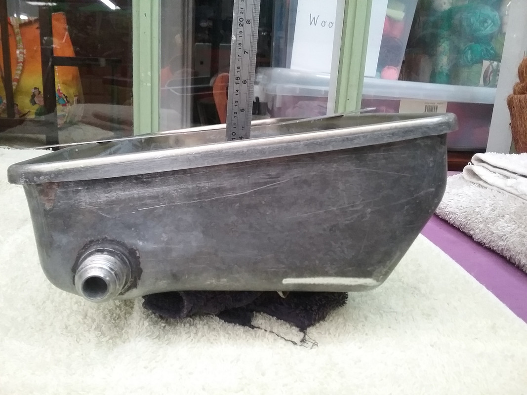
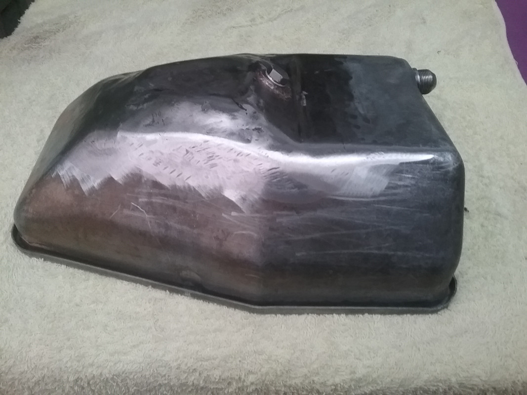
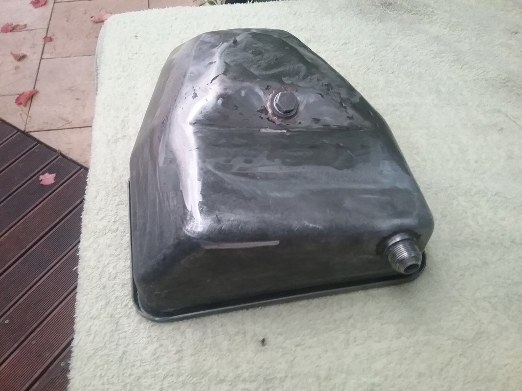
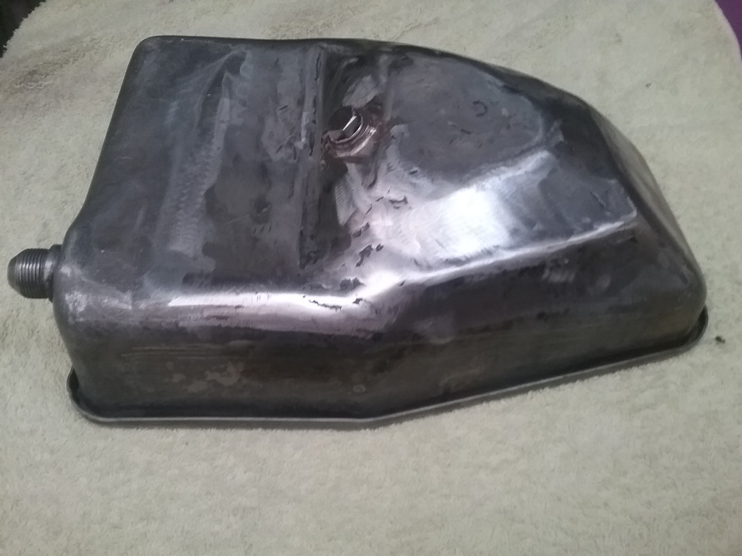
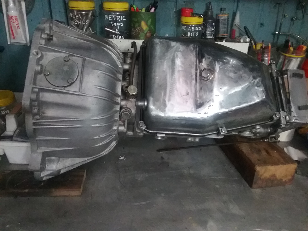
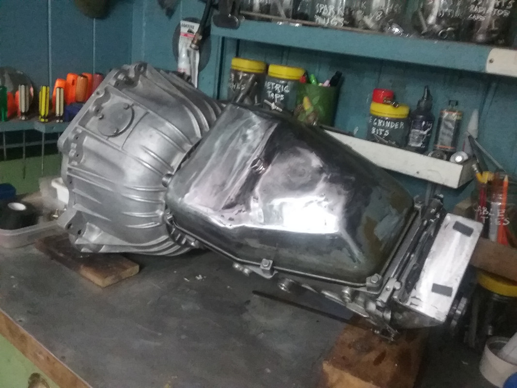
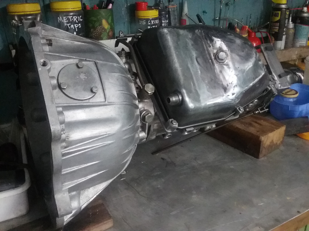
Here's the last few pix of the transmission sitting right way up showing the finished trans pan (trans fluid level will now be correct as will the dipstick reading) and the modified dipstick position (for my vehicle's application). Note: The transmission pan is now no lower than the lowest point of the bellhousing. 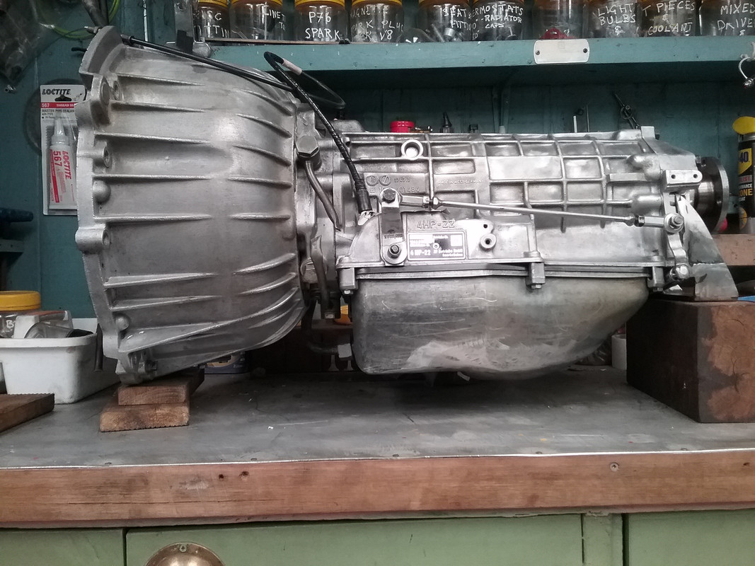 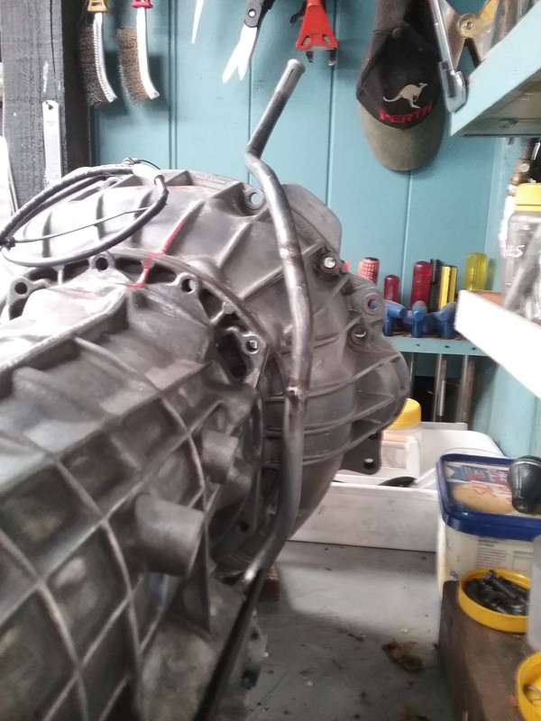 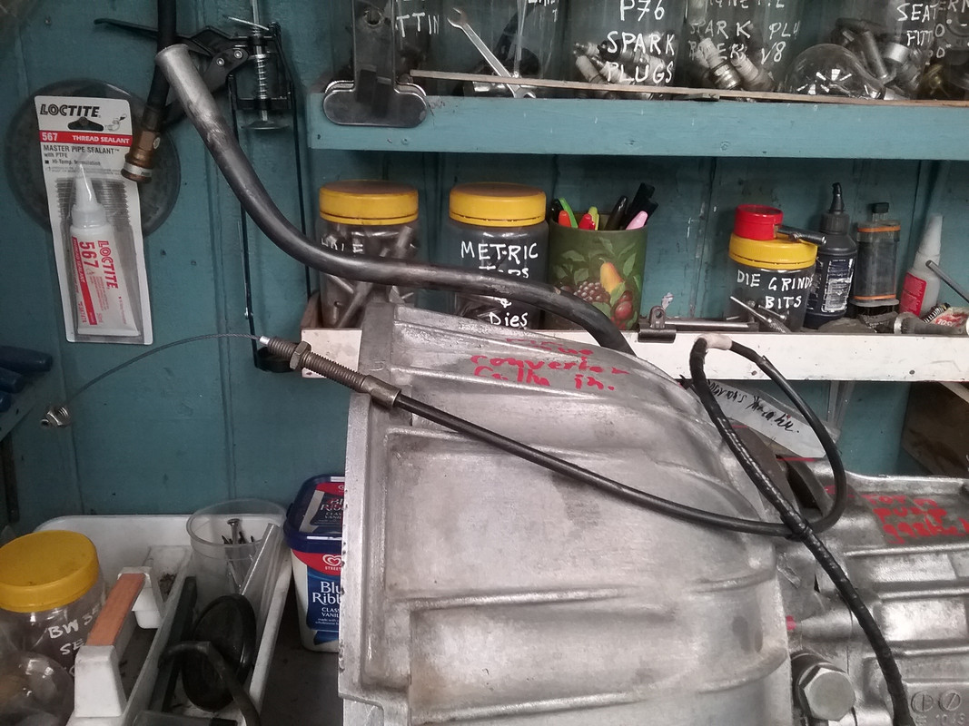 |
|
|
|
Post by johnwp5bcoupe on May 12, 2018 8:32:39 GMT
Good bit of dedicated Shed Engineering as usual Vince  |
|
|
|
Post by enigmas on May 12, 2018 12:31:43 GMT
Good bit of dedicated Shed Engineering as usual Vince Thanks John...well at least my wife knows where I am and what I'm doing! |
|
|
|
Post by johnwp5bcoupe on May 12, 2018 14:20:45 GMT
Good bit of dedicated Shed Engineering as usual Vince Thanks John...well at least my wife knows where I am and what I'm doing! Yep mine too lol!! |
|
|
|
Post by enigmas on May 22, 2018 9:46:03 GMT
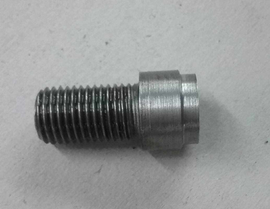
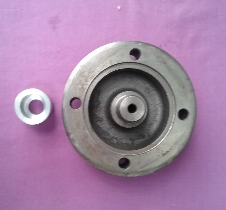
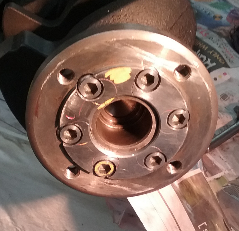
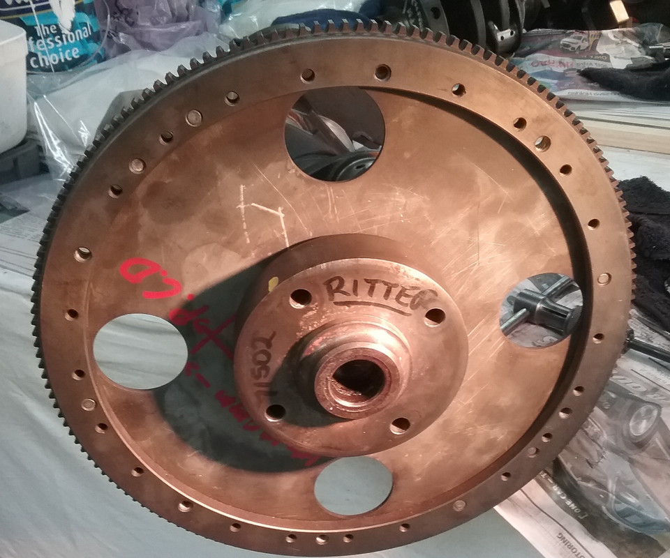
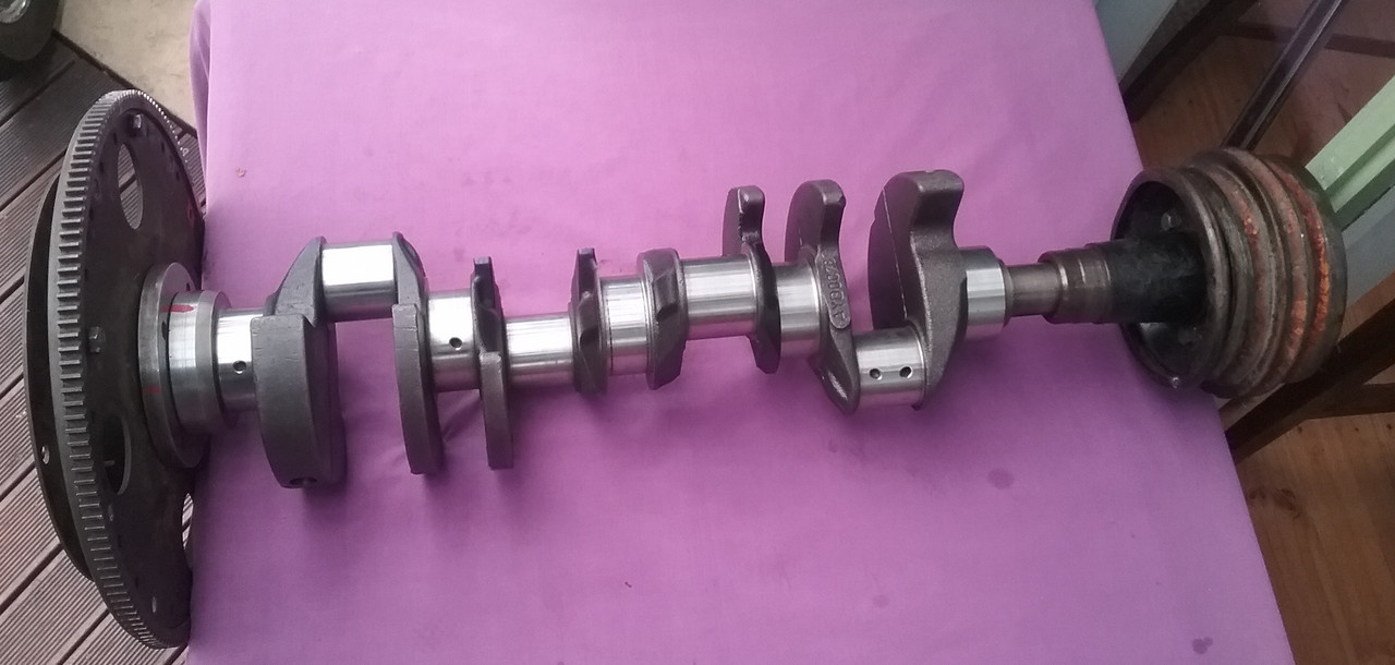
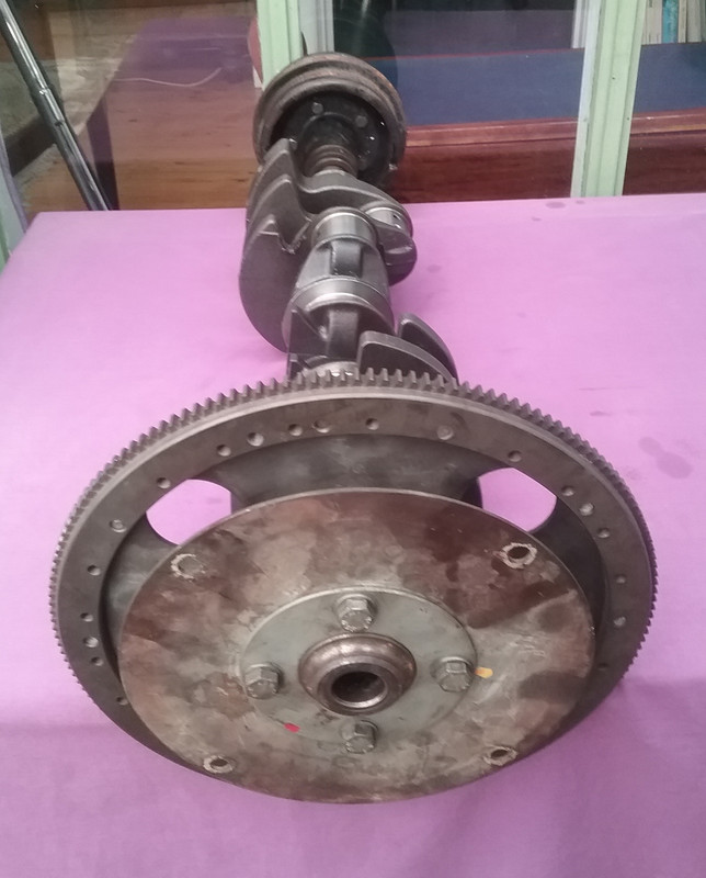
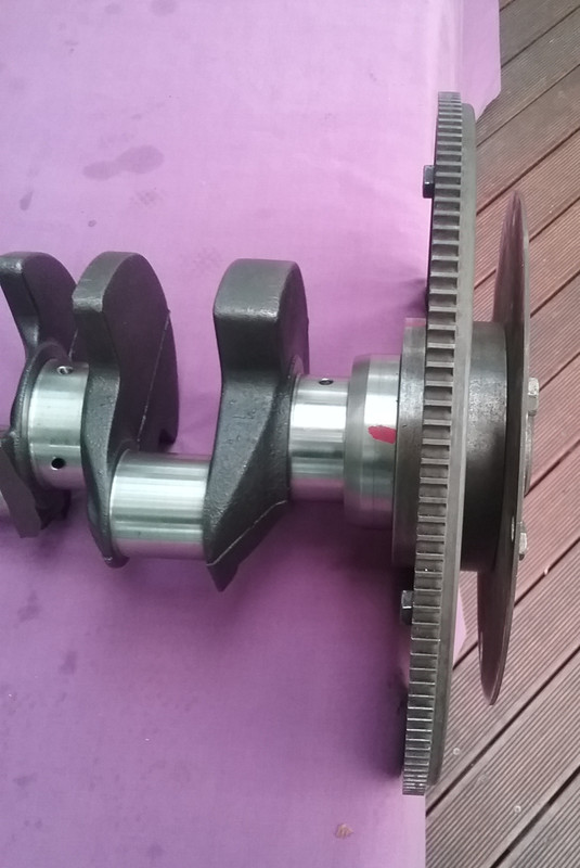
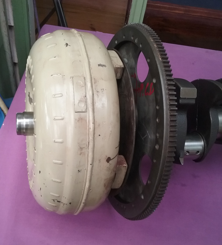
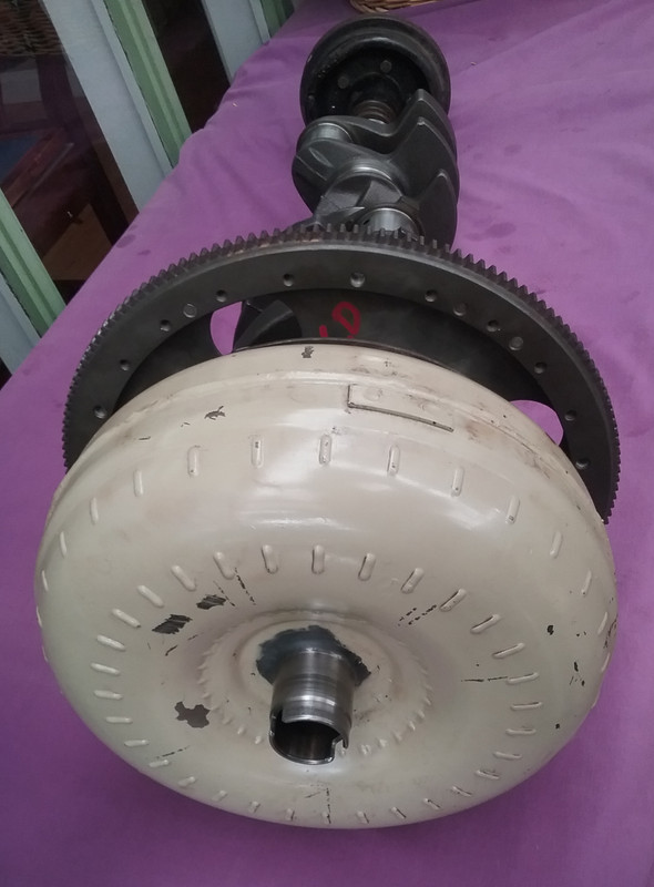
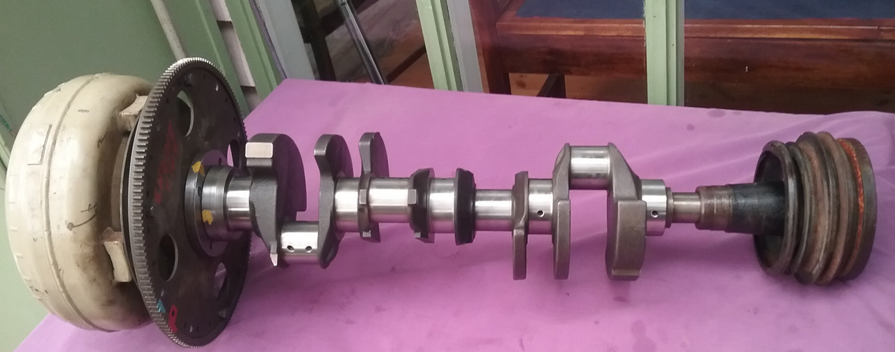
ZF Adaptor Modification (x1)Note: This modification to the (Range/Land Rover V8) ZF4HP22 Crankshaft Flange adaptor is only relevant if fitting this transmission to a 4.4 litre Leyland P76 V8 (as found in OZ.) As my P5 Coupe is fitted with this engine the modification to the adaptor is necessary.Some Technical Trivia. Drive/flex plates for starter engagement. Although the Rover driveplate is flat and the P76 V8 driveplate is dished they both place the ring gear in the same relative positions. Measuring from both engine's crankshaft flanges to the edge of the drive gear teeth is exactly 1/2" for both the Rover and the P76 V8. My car utilizes the small Range Rover gear reduction starter motor on the P76 ring gear. ZF Adaptor Modification. There are several adaptor component pieces for the ZF application. The modification is made to the piece that directly bolts to the crankshaft flange of the Rover V8. The modification is required due to the differing PCD (pitch circle diameter) bolt arrangements between the Rover V8 crankshaft flange and the P76 Flange. The following diagrams/pix illustrates the differences. 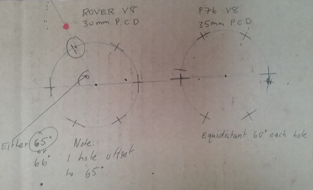 Note: One hole on the adaptor for the Rover crankshaft flange is offset! All holes on the P76 crankshaft flange are equidistant and all spaced at 60°. The crankshaft spigot is a larger diameter on the P76 V8  The Rover ZF adaptor and a mild steel bar machined to create suitable press fit plugs. 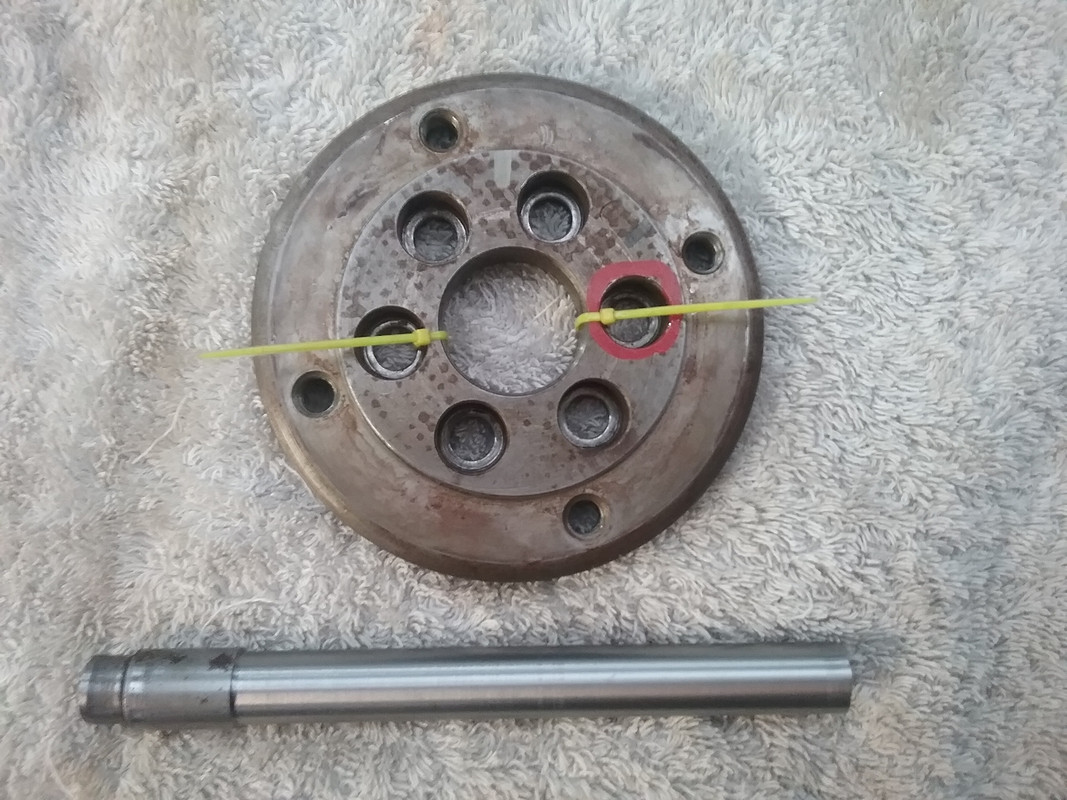 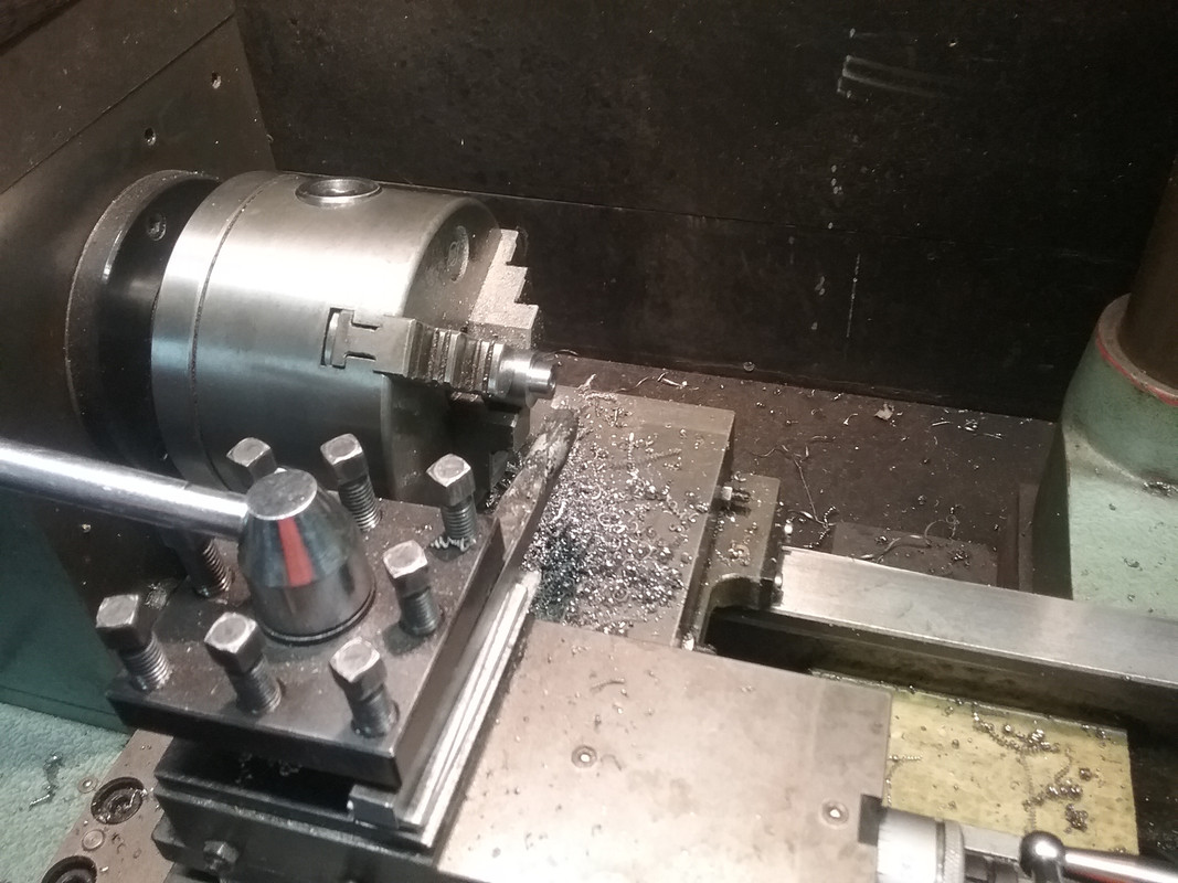 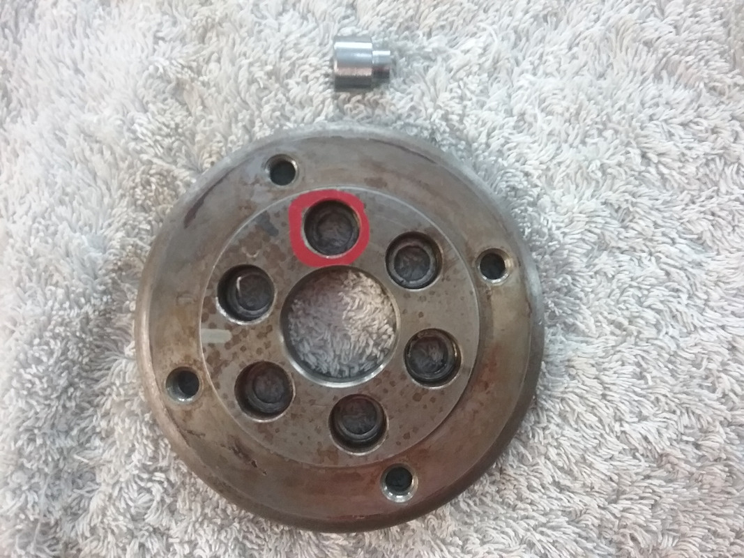 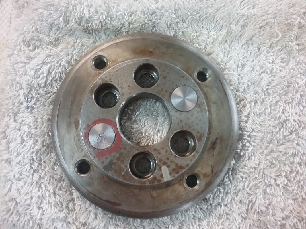 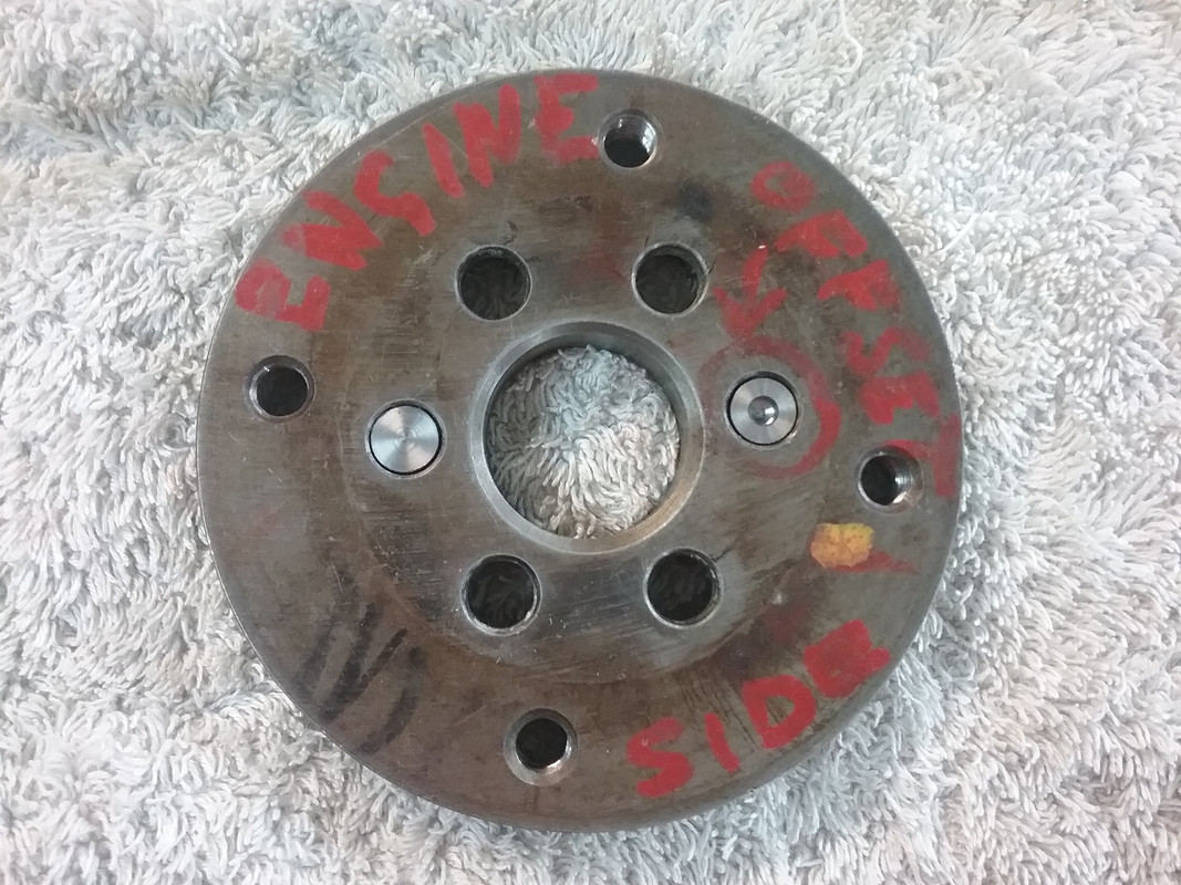 The hole in one of the press-in plugs is the centering hole, when the bar was machined to diameter. * When all the plugs are pressed into place the countersunk holes will be redrilled to suit the larger PCD of the P76 crankshaft flange.
|
|
|
|
Post by enigmas on May 23, 2018 11:52:17 GMT
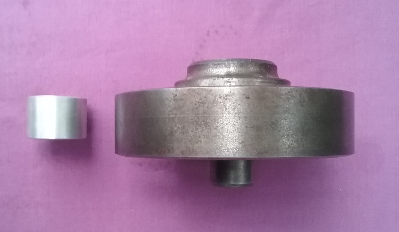
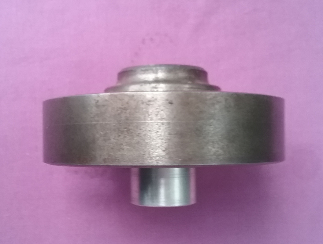
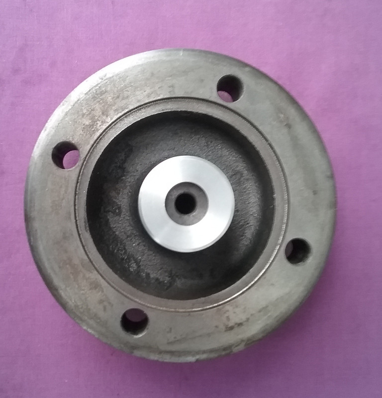
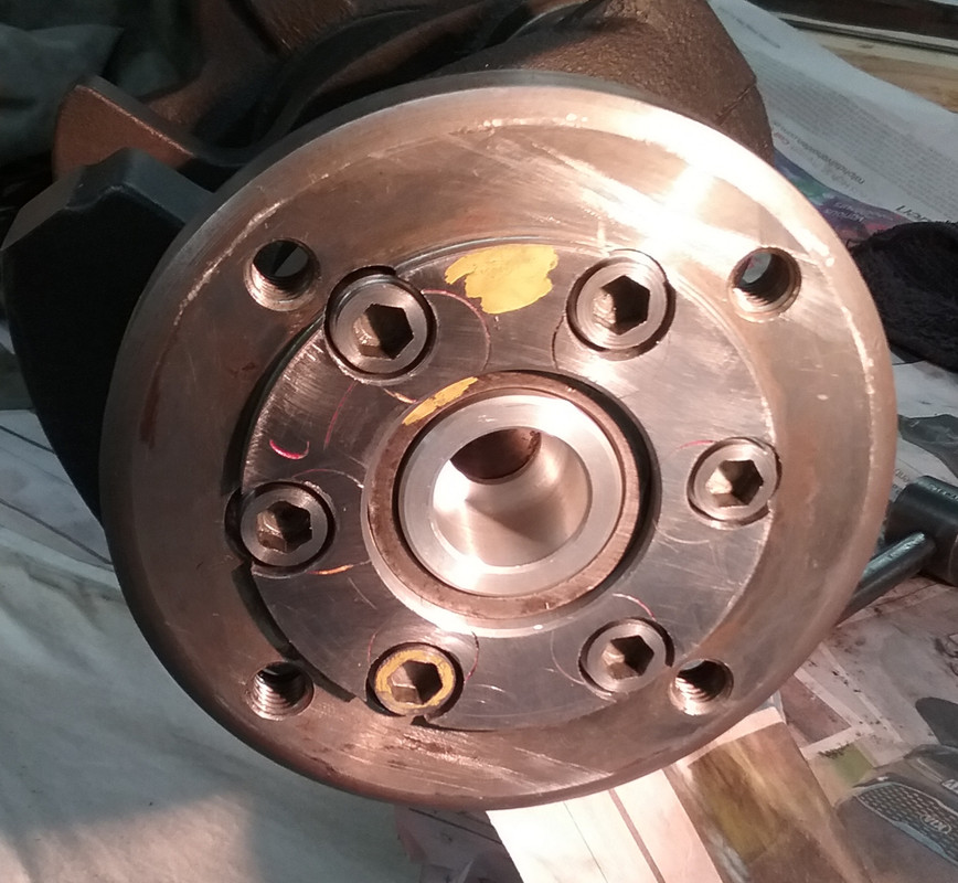
ZF Adaptor Modification (x2)I put a bit more work into the ZF to P76 adaptor today fitting the remaining pressed in plugs, machining the spigot hole larger for the P76 flange and levelling the face where the plugs protruded slightly. 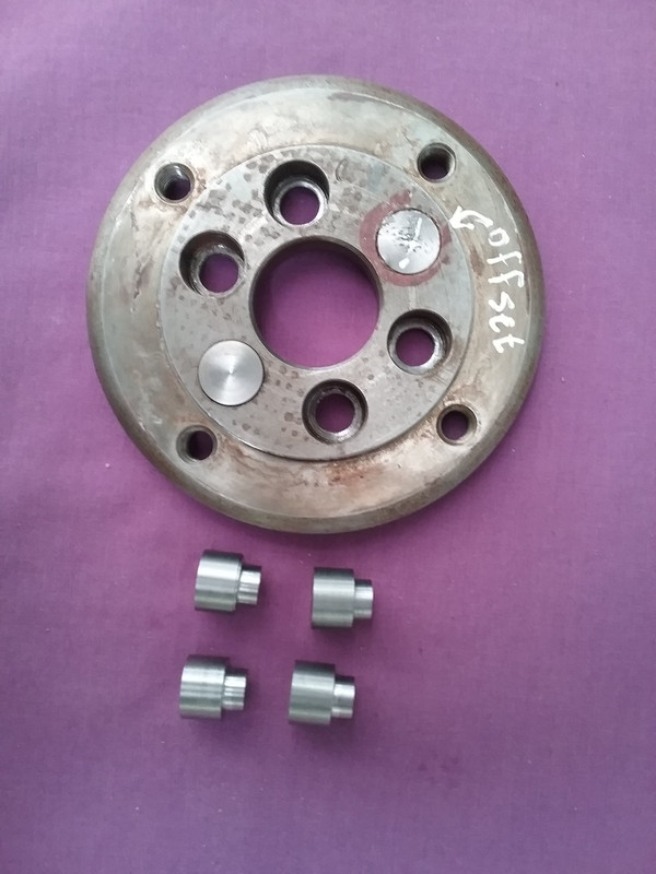 Note the difference in the hole for the crankshaft flange spigot between the Rover and the P76. 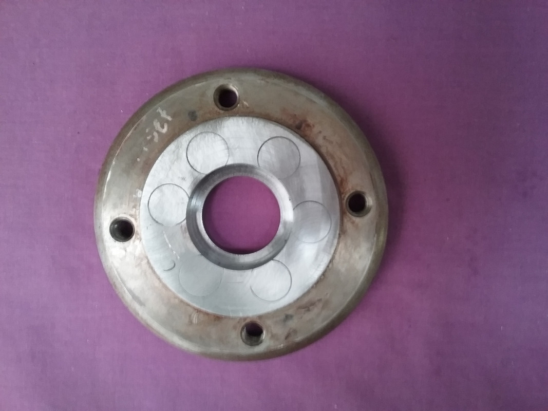 This is the adaptor with the spigot hole machined to size for the P76 crankshaft flange. 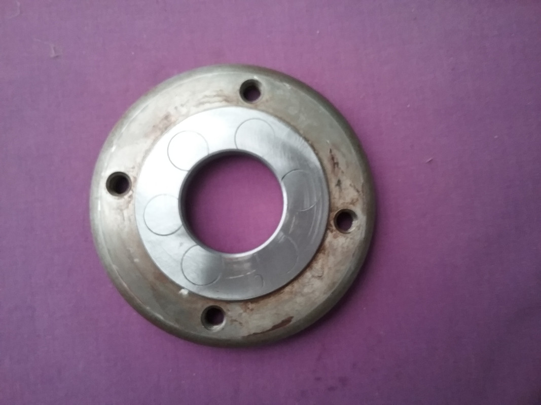 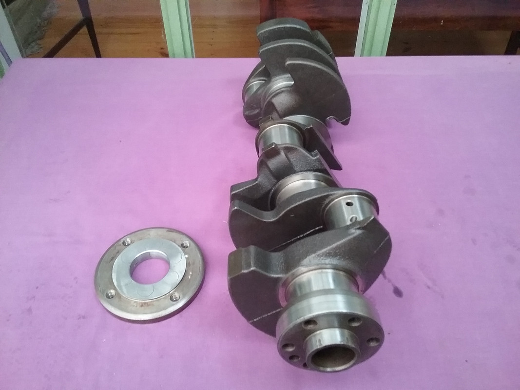 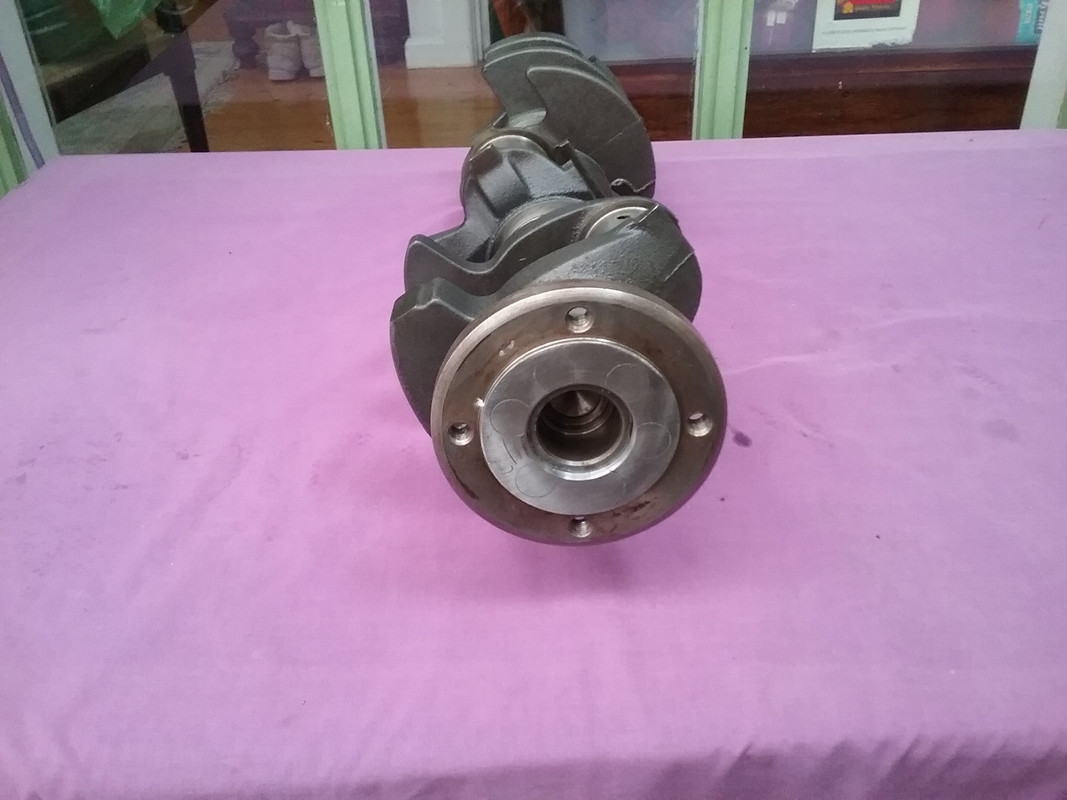  The last remaining task is to mark out the 6 mounting holes at the P76s larger PCD. All holes are set at 60°.
|
|
|
|
Post by enigmas on May 24, 2018 6:02:01 GMT
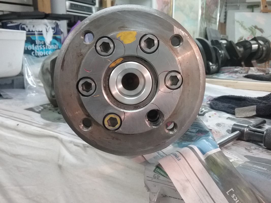
ZF Adaptor Modification (x3)Setting out the P76 Crankshaft Flange PCD on the ZF adaptor. I spent about 2.5 - 3 hrs today marking out where the holes should go. A task like this can be nerve wracking, as a slight error in measurement, marking out, centre punching holes and then drilling them through (incrementally) can lead to a screw-up! My tools for this are pretty basic, including: a good millimeter/imperial steel ruler, 2 plastic protractors, an accurate pair of dividers, a scriber and a paint pen. I did have a few moments where I thought I should take it to an engineering firm that had an indexing head, to ensure the holes were accurately placed...but I recovered from that! The previous day I'd machined a large aluminium plug for the centre hole of the adaptor, also adding a tiny centre hole in the plug for marking out (scribing) the PCD of the bolt holes. Tech Trivia. An interesting side note for the tech heads. The P76 V8 crankshaft flange bolt pattern PCD is 70mm. The radius then is 35mm. The 6 holes are spaced evenly at 60°. The distance between each hole (measuring centre to centre around the perimeter is exactly 35mm...exactly the same as the radius. That can't be a coincidence! Here are the pix of todays effort. The adaptor now bolts on but only grips by a couple of threads. 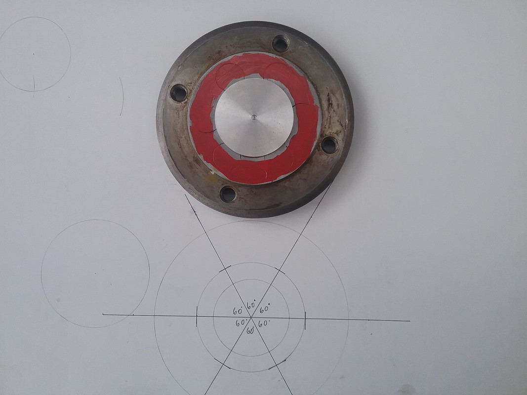 Scribed hole placement. 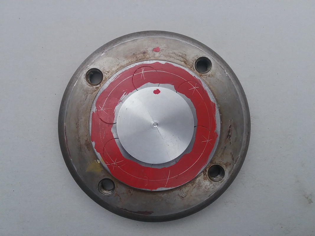 Centre- punched for holes. 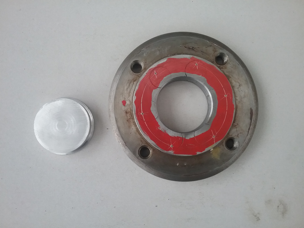 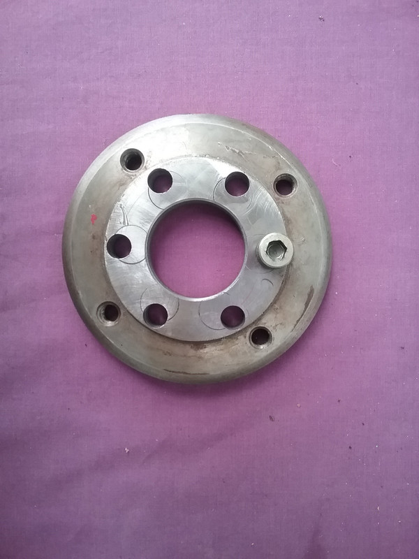 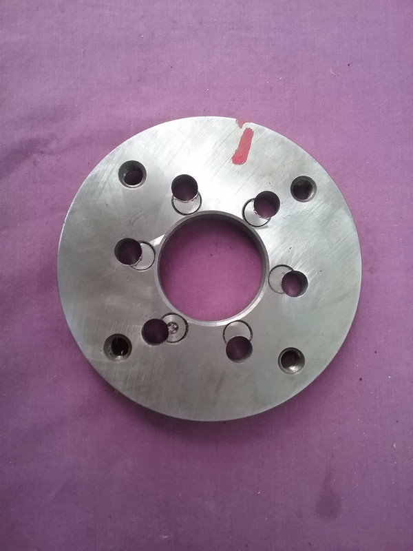 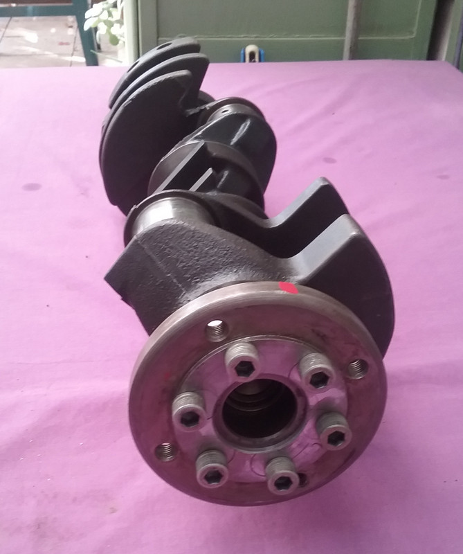  The Final Task. I need to drill the holes out to 5/8" diameter but stop at .200" from the base, then square off the hole. The socket head bolts will then sit in a cavity and be flush with the outer face of the adaptor.
|
|
|
|
Post by johnwp5bcoupe on May 24, 2018 9:25:02 GMT
You should have posted it to me Vince I could have Indexed it out for you |
|
|
|
Post by enigmas on May 24, 2018 14:08:19 GMT
You should have posted it to me Vince I could have Indexed it out for you Well thanks John...I'll take a rain check on that for my next project.  NB. Kind of unbelievable how accurate a couple of cheap school boy protractors are! I thought one of the holes might have been slightly out but they all screwed straight into place. |
|
|
|
Post by johnwp5bcoupe on May 24, 2018 16:12:28 GMT
If you take the time and effort it pays off Vince well done! I would cheat and use a dividing head |
|
|
|
Post by enigmas on May 29, 2018 9:54:17 GMT
|
|
|
|
Post by enigmas on May 30, 2018 4:11:02 GMT
|
|