|
|
Post by djm16 on Mar 26, 2020 4:34:22 GMT
Next was installing the inlet rockers. Oil is injected into the rocker shaft through a hole in the rocker shaft pedestal. I was surprised to see how rough the mating surface is that is supposed to seal against the head, so I used a smear of 515 to ensure that more of the limited volume of oil that can squeeze through the flow limiting hole in the head banjo bolt actually reaches the rockers. I guess it can't have been all that bad as there was no discernible play in the inlet rockers, unlike the exhaust. Smear of 515.  Trace of moly grease.  Assembly lube (both ends of the pushrods).  It was interesting that pushrods to cylinders 1 and 2 would not go through the passages in the head once the head was placed on the block, I think the head gasket was holding them up. So I had to loosen off the head bolts and lift the head a fraction to get them through. Other than that, getting the head on and torquing it down was pretty straightforwards. I even remembered the water pump O-ring and the generator mount this time. |
|
|
|
Post by enigmas on Mar 26, 2020 9:36:00 GMT
I'm not trying to rain on your parade David but why didn't you have modern hat seals fitted to the tops of the valve guides when the head was at the machine shop. I'd be very careful about compromising the collets ability to lock onto the grooves on the valve stem for obvious reasons.
|
|
|
|
Post by djm16 on Mar 27, 2020 10:13:11 GMT
Why not top hat seals?
I did think about it, but came to the conclusion that turning down the top of the valve guides to take the seals would leave insufficient metal at the top of the guide as the O-ring slot is only a few mm down from the top.
Also, even with worn guides, damaged O-rings and a missing O-ring, there really was no discernible blue smoke from the exhaust.
|
|
|
|
Post by 3litrekiwi on Mar 28, 2020 8:37:11 GMT
My refurbished engine is still burning more oil than I would like however I have done less than 500 miles so hoping that my rings are still bedding in and the oil isn't leaking down the guides. When I tidied up the head I fitted modern valve seals. These are viton with three lips as opposed to a single one if the original o ring is fitted, even if viton is used rather than the original nitrile rubber. You are right David that the o ring grooves outer diameter is close to the diameter required to fit the hat seals. Thing is though, I felt I needed to lose a bit of height from the guides anyway so there was sufficient clearance between the collets and the top of the seals. The overall height of the guides with the new seals fitted is almost the same as the original guides if the original guides are machined to remove the groove. One other potential advantage is the seals could be replaced without removing the head using rope or compressed air.  Sorry, I haven't got a photo of the seals on the guides but the actual loss of bearing length is less than 2mm, probably more like 1. Martin |
|
|
|
Post by djm16 on Mar 28, 2020 15:34:36 GMT
Thanks for your comments about the top hat seals. My head is done now so it will be interesting to see how just new O-rings gets on.
If your exhaust guides are worn enough, you can certainly suck enough oil up them to give blue smoke on the over-run. That was the trigger for my extensive article on exhaust valves (and guides).
|
|
|
|
Post by djm16 on Jan 31, 2021 3:30:05 GMT
My goodness, it is nearly a year since I last posted. I have been active, but working on the engine compartment instead. I am now at the point of final checks before possibly putting the engine back in next week. I am hoping for a cool day as I am sure that my brain will overheat with the necessary concentration. Apart from checking the gearbox for static leaks, I thought that I would do one last check of the cam timing. I had set up the timing using a printed circular indicator zeroed on TDC rather that the timing mark on the flywheel, largely because at that point I did not have the bell housing attached. Now I find that I am missing the timing pointer. So I have taken photos at flywheel positions just before and after EP as indicated by a dial gauge.    These look "about right" compared to the drawings in a manual. Q1. Close enough? Q2. If cam timing is a degree or so early, will I even know the difference? |
|
|
|
Post by djm16 on May 23, 2021 4:19:12 GMT
There was a bit of a delay getting the engine back in. Just a couple of days after my last post, the worst bushfire in WA for more than 50 years swept through our property (see bushfire on Youtube). We stayed to defend and saved the house. The volunteer fire brigade saw our lights on and came to see what idiots had not evacuated, and stayed to save our two sheds. No way was I abandoning the property, not after the hundreds of hours that have gone into the 3 litre (and others). I did finally get the engine back in. It starts and runs very nicely and I have had a couple of excursions up and down the drive. The car will need inspecting again as I handed in the plates right at the start as I knew it would be a long job. So it became essential to fix all the oil leaks including the diff pinion. But on removing the rear prop shaft it was apparent that the pinion bearings were faulty, the drive flange was both stiff and graunchy to turn. So the original engine rebuild has now turned into a diff rebuild (another thread). |
|
|
|
Post by 3litrekiwi on Sept 26, 2021 8:44:53 GMT
Did you remove that tube David? I was going to use my collet chuck with a draw hammer but my 12mm collet won't grip it so will need to make a bush and use a larger collet. I am assuming the tube is pressed into the crankcase.
|
|
|
|
Post by enigmas on Sept 27, 2021 0:18:31 GMT
I certainly commend you both for your persistence with the Rover designed IOE 3 litre 6 cyl engines. It seems that once tired and worn there's no end to the myriad problems. Obviously there's no joy in having to pull these engine's out repeatedly.
I know with side valve engines (air & liquid cooled) there's always cylinder induced distortion due to the exhaust being channelled through the block. Any distortion leads to poor ring seal followed by a haze of blue smoke. Have either of you (3litrekiwi & DJM16) considered freeing up the exhaust flow through and from the block. Poilishing the exhaust ports within the block, fabricating a free flowing individual port exhaust manifold and fitting less restrictive mufflers. I'm sure the cast iron manifold bolted to the side of the cylinder head doesn't help especially in hotter climates.
Just a few random thoughts. 🤔
|
|
|
|
Post by 3litrekiwi on Sept 29, 2023 8:48:08 GMT
Hi
I'm back onto my spare engine. After almost two years at the machine shop it is bored to suit my new pistons, the top has been machined and the valve seats reground.
The pistons are Repco brand with chrome top rings which I am a bit ambivalent about however the reconditioner recons these were ok back when they were produced. The new pistons are 582 grams with pins. They are all within 2g of each other so pretty good there. The originals are 508g. As David commented about the JP pistons, the main difference is the gudgeons. The difference is about 50 grams due to the originals being a 5/8 bore, the Repco ones are 1/2".
I have yet another engine, so access to a set of used pins. The two second hand pins that I have on hand don't seem worn at all, my question is will the 80 gram increase in mass make much difference in terms of vibration and would it be a good idea to use the lighter pins?
Cheers
Martin
|
|
|
|
Post by enigmas on Sept 29, 2023 23:38:36 GMT
I believe the balance will be fine Martin, the only issue if it is an issue is there will be more kinetic energy and mass from the slightly heavier pistons, so there's more load on the conrods at the extreme ends of the stroke when the pistons reverse direction. But as I don't believe you'll be revving the absolute ring out of this engine in normal use, I don't see it as an issue. Not for the tech averse but my Italian friend in this interesting video outling 6 cyl engine balance may clear up any concerns you have. As an aside I prefer the lightest piston weight where possible for the above reasons, but I am dealing with old engines that have seen a few life times of use; so less stress on older components. This is an option below but it's not for the faint hearted. Differing piston weights 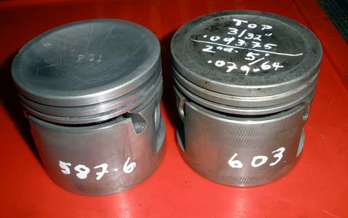 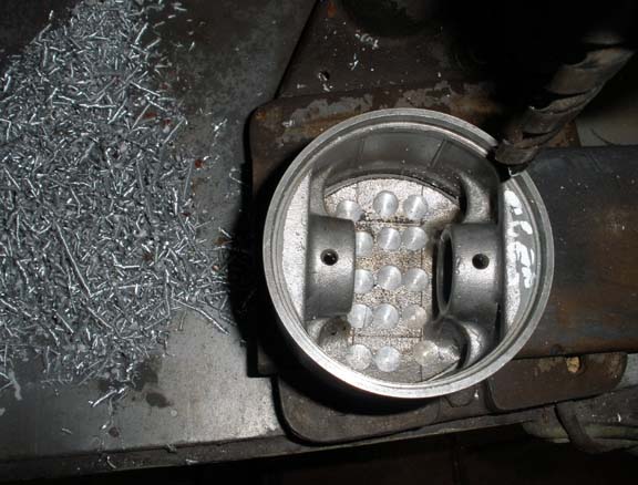  Here's the Youtube Video re: 6 Cyl Engine Balance |
|
|
|
Post by 3litrekiwi on Sept 30, 2023 20:00:58 GMT
Thanks Vince, I agree that these are not what you might call an engine designed for high revs. I have other vehicles for more spirited driving or riding.
|
|
|
|
Post by 3litrekiwi on Nov 9, 2023 9:02:59 GMT
I got my lower rocker shafts back from the hardening shop yesterday and they are great. Nitriding should have produced a very hard surface, they have not increased in size and are still nice and straight. The rockers are an amazingly good fit given how worn the old shafts were. I’ve made a set of upper rocker shaft bushes but the shaft was a bridge too far. That and the rest of the bits and pieces to finish my rebuild should be here from Wadhams within the next week or so.  |
|
|
|
Post by 3litrekiwi on Nov 23, 2023 8:28:46 GMT
I have refitted the cam and lower rockers. Really pleased with the fit after a bit of modification. I know we consider these a quality vehicle for the time but I must say that with an engineering background the way that the rockers are aligned with the cam and exhaust valves doesn't seem very good design or machining practice. The rockers are in pairs with a spring to press the pair to one side of the housing. No problem with that, however the shim washer arrangement to align the rockers with both the cam lobes and exhaust valves leaves a bit to be desired. I can't see why these locating surfaces could not have been machined more accurately. I have a mixture of 0.018" shim washers, 0.09" and 0.178" Quite a variation. A datum from the centre of each exhaust valve would have been a possibility or even from the front of the block based on the cylinder spacing. At the very least there should have been a minimum dimension from the valve centre to the bearing face. The biggest problem was #5 rocker would not align with the valve with no shim. Metals of the same type working on each other tend to weld together so some shim is required. This is the alignment with no shim washer at all.  I just couldn't assemble it like this so decided to machine a bit off each rocker and fit an 0.018" washer to separate them. I made an expanding mandrel and took 0.02" off both rockers, at the face that bears on the washer. This was the result.  I'm happy with the alignment now but it does mean that any future mechanic will need to keep the rockers in the order they are in now. Cheers Martin |
|
|
|
Post by enigmas on Nov 24, 2023 10:19:02 GMT
My refurbished engine is still burning more oil than I would like however I have done less than 500 miles so hoping that my rings are still bedding in and the oil isn't leaking down the guides. When I tidied up the head I fitted modern valve seals. These are;viton with three lips as opposed to a single one if the original o ring is fitted, even if viton is used rather than the original nitrile rubber. You are right David that the o ring grooves outer diameter is close to the diameter required to fit the hat seals. Thing is though, I felt I needed to lose a bit of height from the guides anyway so there was sufficient clearance between the collets and the top of the seals. The overall height of the guides with the new seals fitted is almost the same as the original guides if the original guides are machined to remove the groove. Martin PISTON RING GAP. This Youtube Video may be of interest, especially the discussion relating to the difference in gap between the Top and Second ring. Jump to 5.30 on the video if you don't want to listen to the initial part of the conversation. |
|
|
|
Post by 3litrekiwi on Nov 24, 2023 20:41:19 GMT
Thanks Vince
Interesting discussion. The rings in my new motor are gapped at the bottom of the WSM tolerance. Out of the box they were less than the reccommended 15 to 20 thou so I gapped them to 15 or a bit more but certainly nowhere near 20. After watching this, as I have nothing else to do until my parts arrive, I am tempted to pull the pistons again and increase the second gap to 20. I had thought the less gap the better for sealing.
One thing about the discussion though, a high performance race engine and the long stroke ioe engine are not the same species.
|
|
|
|
Post by 3litrekiwi on Jan 3, 2024 22:41:09 GMT
Hi David (or anyone else!)
I am going to be doing my engine swap on Monday or at least making a start. Reading the WSM there seem to be a few points that are not immediately logical. As you have relatively recently done this job, perhaps you could enlighten me and perhaps save a bit of time.
I assume the removal of the heater is to prevent damage to it when lifting the engine as the access to the bell housing bolts would be from inside with the floor section removed. With the bonnet lock platform removed I had thought the engine would only need to come up to clear the sump and a bit of plywood taped to the heater would protect it however removing it is not a big deal and I have already refurbished it once so don't want to risk damage.
I don't understand why the gear change lever assembly would need to be removed, some advice on this would be appreciated. The bell housing is all studs so it would seem that the engine should separate from the gearbox with the gearbox left intact.
Similarly dismantling the rear gearbox mount would leave the gearbox effectively loose. I can see that loosening the through bolt to allow the gearbox to move up and down a bit might be useful.
My plan was to remove the PS pump from the back of the generator rather than disconnecting the oil lines, can you see why this would be problematic?
Also the WSM says to remove the brake booster, the clearance between the bell housing and the booster is tight but it looks like if the booster mounts were undone this might enable the bell housing to get past with a towel between both parts. My plan was to unbolt the mount bracket from the block and leave the drivers side mount in the car.
I have replaced all the engine mounts in situ when I did the gearbox and was planning on lifting the engine in without the mounts at least on the rear to enable a bit more side to side clearance. I do recall a lot of frustration when fitting the drivers side mount getting at the bolts but it was possible.
The WSM also says to remove the oil filter housing which doesn't project much further than the starter motor and therefore the bell housing. I guess this will be apparent as the old engine comes out and is easy enough to take off with the engine on the hoist.
Any advice on these points or anything else to do with the job will be much appreciated.
Martin
|
|
|
|
Post by MK IA Norway Viking on Jan 4, 2024 8:12:58 GMT
Instead of lifting the engine out it will be considerably easier to take out the subframe complete with ALL mechanicals. It is simple; undo the six bolts holding the subframe to the chassis, disconnect all items that extend from the torpedo to the "mechanicals" sitting on the subframe (pipe from the master brake cylinder, exhaust gas pipe, gearbox lever and so on, plus the intermediate drive shaft at the rear of the gearbox etc.).
If you can lift up the car, the subframe will be standing on the floor and this gives you immediate access to engine and everything else that's mounted to the subframe.
If you cannot lift up the car more than "a little", remove the front grille and radiator and the cross-members below and above the grille to create a "passage" for the engine to pass through as you pull it "out" of the engine bay.
I believe this is the method that Rover intended, whenever there was an engine-out scenario for maintenance and repairs.
Good luck with your project.
|
|
|
|
Post by Phil Nottingham on Jan 4, 2024 10:03:25 GMT
Instead of lifting the engine out it will be considerably easier to take out the subframe complete with ALL mechanicals. It is simple; undo the six bolts holding the subframe to the chassis, disconnect all items that extend from the torpedo to the "mechanicals" sitting on the subframe (pipe from the master brake cylinder, exhaust gas pipe, gearbox lever and so on, plus the intermediate drive shaft at the rear of the gearbox etc.). If you can lift up the car, the subframe will be standing on the floor and this gives you immediate access to engine and everything else that's mounted to the subframe. If you cannot lift up the car more than "a little", remove the front grille and radiator and the cross-members below and above the grille to create a "passage" for the engine to pass through as you pull it "out" of the engine bay. I believe this is the method that Rover intended, whenever there was an engine-out scenario for maintenance and repairs. Good luck with your project. The below the grill X member to which the front valence in bolted spot welded in so cannot be removed unless cut. I suppose plates could be made to make it removable. Rover did not think it worthwhile however |
|
|
|
Post by 3litrekiwi on Jan 11, 2024 4:52:14 GMT
Thanks for the suggestions, I don't have room to remove the body from the sub frame so have pulled the engine out thought the front aperture after removing the grille and bonnet cross member. apart from the sod of a job removing the drivers side engine mount, which
I expected having replaced the rear engine mounts previously the job went well.
My driveway is steep from the front of my garage so once I had the engine out, with no room to move, I had to roll the car out, park the old engine outside for the time being and pull the car back in with a chain block.
So for future search reference, the engine can come out with the booster in place, no paint was removed so there is enough clearance.
Taking the PS pump off is an option rather than disconnecting the hoses however it is best to take the HP support bracket off to give old hoses more flex. Mine looks a bit past it's best so after all I will replace it with a much more youthful spare that is in the spares box.
The heater does need to come out.
The rear gearbox mount doesn't need to be loosened other than the center bolt to allow a bit of unfettered up and down movement however the engine came forward without much upward movement of the gearbox.
The engine bay is nice and clean and I have taken the opportunity to reloom the engine bay wiring as the old cotton weave was falling to bits in many places. I will post some photos once the job is complete.
I suspect the alignment of the motor and gearbox is going to be fun with such a heavy lump. Tomorrow or Saturday I will know for sure.
Taking the PS pump off was a timely opportunity to replace the flogged out drive adaptor. Fortunately I have a good spare, both the spare and the one that came out of the car were dry. I am tempted to assemble the pump with a bit of appropriate grease on the surfaces, the WSM doesn't seem to mention this, once again, any advice? I am assuming that the steel drive dogs and rubber liner are supposed to be separate parts as the alternative is I have two worn out ones, one much less than the other.
|
|
|
|
Post by 3litrekiwi on Jan 26, 2024 22:05:03 GMT
Job pretty much done. Just the bonnet to go on once the weather clears later today.   I took the opportunity to reinstate the rear heater plumbing which was missing when I bought the car. The old rubber hoses from front to rear were still there however the engine bay pipes were long gone. Quite a mission to thread a tube from the heater tap to above the torsion bar. Not so bad for the return line back to the firewall elbow. I ran 1/2" copper tube with nipples silfosed into the ends. The tube from the heater took a couple of goes but it looks like it should be there. Not a lot of tolerance on the bends to clear the hand brake and accelerator linkages. The front to rear rubber hoses were impresssively hard however one of the outer composite trunking is in surprisingly good condition. For the time being the outward line is in the original trunking but the return a naked rubber . The stiffnes of the trunking on one holds its shape quite well so I have put an extra SS cable tie half way between each body mount which keeps the more floppy rubber heater hose paralell. I assembled as much as possible prior to lifting it in with both manifolds, the starter, generator squeezing past everything left in the engine bay ok. The only casualty was a wee bit of paint transferred from the PS reservoir to the exhaust manifold, since touched up. My original radiator became a spare, as I had picked up a unit that looks to have been recored. Might as well have the better one in use. Once fitted, the bonnet cross member was a bit tatty around the fixing points so that got a rub down and a new coat of paint along with the header tank to match the rest of the black bits on the engine. Surprising how different satin blacks can be however when I was powder coating we had over 40 different black powders. I have only done an initial warm up run of about 20 km so that the inlet tappets could be set which went well and it is pleasing how quiet the refurbished engine is. Getting rid of all the wear from all the rocker shafts seems to make quite a difference. Similarly, I think that dressing the wear off the rockers where they contact the valves has made accurate clearance setting a lot easier. As always seems to be the case, another issue presented on the initial run. The replacement engine had a new clutch so I fitted it rather than using the one off rhe original which was also a relatively new one. Pretty disappointing to find that this one has a pretty bad judder. I am hopeful that it will wear in as there are plenty of stories on the net that this is likely. Otherwise it will be another day of spanner work swapping it for either the prevoius one or another new one. Fortunately, there are two brand new ones in boxes and three good second hand sets on my parts shelf. Cheers Martin |
|
|
|
Post by Phil Nottingham on Jan 27, 2024 6:55:55 GMT
I used black flexible plastic cable conduit to run the 1/2" heater pipes in. It provides little support but good protection and support underneath the floor.
|
|
|
|
Post by 3litrekiwi on Jan 30, 2024 23:47:07 GMT
Now that the new engine is in, time to sort out the various parts and decide what to keep and what to send to the scrappie. The obvious place to start seemed to liberate the good bits from my original engine and get rid of he cracked block. It is a shame that someone had damaged it prior to my ownership by forcing new exhaust valve seats in resulting in three cracks, one part way down #5 bore as at 160k miles the bores are not very worn at all. Last night I made a start pulling the head to keep as a good spare and made an interesting discovery. I suspect #1 big end is going to be somewhat damaged due to carbon build up from the last 10 000 miles or so since I had the head off. Oil consumption has been pretty high but I had not thought about carbon building up to the point that the pistons met the head. #1 was worst but others were not that far behind. The fuel mixture was set correctly and I have been getting 24 MPG on any trips which is better than the literature states.   I measured from the deck down to a clean part of the piston which is 0.047" then there would be the thickness of the head gasket so with the inlet valve 0.030" below the surface of the head when everything is cold there is room for a fair thickness of carbon. I measured the build up on the valve as best as possible and got about 0.065" so the piston and con rod must expand quite a bit at operating temperature as there has clearly been interference. I had not noticed any knock when it was running but perhaps it was only connecting at higher revs. It would seem that for these engines with high miles on them, given that they probably all use a bit of oil, that a de-coke either manually or using a chemical treatment might be a good idea. If this were left, something was going to break at some point. The only noticeable smoke I saw was on overrun after a hill but that is not to say there wasn't some at other times. I was getting about 100 miles per pint. |
|
|
|
Post by 3litrekiwi on Feb 12, 2024 6:07:12 GMT
The new engine is great, 120 miles and no change in oil level. It is nice and quiet and the car is much nicer to drive. I had thought that the old engine performed ok other than the oil consumption but the compression was only ever around 140psi and I think the new pistons and rings are doing a much better job.
The job was not finished with the engine in though. The clutch on the replacement motor was almost new so I decided to use it rather than the original which was still pretty good. I had a brand new set that is now in the car but decided to keep that for someone else in the future.
Bad decision.
The first runs told me that the engine was great but the clutch was not doing it any good as it juddered really badly and on the second run after checking all the adjustment and adding a bit of travel I had a couple of times when I couldn't get any gears as strangely it was not disengaging properly. I could also feel the clutch dragging between gears so the syncros were working hard.
Nothing for it than to pull the gearbox out.
I was surprised to see that all looked ok when it came apart which is a bit disconcerting. After some discussions with a mate I decided not to machine the flywheel as it looked really good with only a slight witness from the friction material and no discoloration. Machining means sacrificing the two dowels that align and drive the pressure plate as in their wisdom, Rover made these blind so the only way to remove them is by gripping with vice grips or similar and they are had it after extraction. Perhaps there is a better tool for this but I don't have one. Head dowels are similar. Since I had the lathe set up I thought I would give the surface a clean up with a bit of emery cloth and this pointed to the problem.
Although the surface looked fairly clean and I had washed it with solvent, once I started to apply the emery cloth, sticky patches became apparent on the surface.
I had cleaned the clutch plate with solvent prior to fitting it however on closer inspection after finding the residue on the flywheel, there seems to be something that has penetrated into the friction material. It is seeping out, probably when it gets warm. Shame as this was at almost the same thickness as the new one now in the car.
Anyway, the new plate is smooth as butter and the drive to and from the British and European car day yesterday was most enjoyable. We were the only P5 but the turn out of other Rovers was pretty good.
I hope that the spanners can stay in the toolbox for a long time now.
|
|


