|
|
Post by johnwp5bcoupe on Feb 10, 2022 9:41:34 GMT
Johnathan two quad seals back to back will not work! I have tried a few methods before curing the problem! I will PM you.
|
|
|
|
Post by johnwp5bcoupe on Feb 10, 2022 11:07:13 GMT
I bought a new bronze lined steel bush that pressed in ok but closed up so that the shaft was too tight in my opinion but probably would have been ok if I hadn't needed to weld the housing. My thought is the heat shrunk the bore in the aluminium a thou or so. These are going to be available in your kneck of the woods if we can get them down here. They are not oilite as far as i can tell, more like an engine bearing but a full steel diameter shell rather than a split version. The lining is some sort of bronze, might be sintered but solid would be ok in such a slow turning application. In my opinion, if you use a hydraulic lip seal it should be more forgiving of few thou wear in the bushing than the quad seal. The reason that I needed to bore a lot deeper than the free height of the seal was the lips rotate about the axis they flex on and the effective length of the seal becomes longer. Unfortunately I am in the same stage of this project as you so my work is still not proven. I bought a new quad seal for the end cap yesterday and a piece of nitrile sheet to cut a new top cap seal from. Interestingly I measure the thickness of the seal as 1.8mm with the shim that sets the height of 1.5mm. The only sheet material I could get was nominally 1.5mm however when I got home, the sheet measured 1.8mm so should be perfect. The spool needs a couple of special tools to dismantle it and I was going to make them however when I got the shaft out, there doesn't seem to be any reason to strip it right down. I plan on replacing all of the other o rings after I am confident that the box is oil tight. The other reason I decided not to attempt to completely dismantle the spool is there are holes in the valve centre, part K in the WSM that should line up with the inner female inner spool half but I can only get one pair to align so feel that I might do more damage trying to get it apart than any benefit as there are no seals inside and the bearing feels ok. Everything else looks fine. I have a 2300psi gauge on the way so once it I have the box reassembled again, I should be able to make a test rig up and apply pressure similar to the working load and cycle it ro check for leakage before fitting. cheers Martin The Bush will be tight for two reasons it shrinks in diameter when fitted even if you freeze it and heat the box, you will have to Ream it. Did you Line Bore the Shell when the new Bush was fitted? The Camshaft bearings should be checked and adjusted if you want to eliminate any play. If you keep the Roll Pin in line it will all be correct! Your seal should run on part of the shaft that hasn't been used so a few though is no good as the old quad seal is 0.125 so has to be at least that IMHO. Set the bush too far in the box and the Bush will foul on the Rocker Shaft when adjusting the Worm. The box will split at the rear if over pressured for sure! I think reading from what you have done you may have a problem at no pressure? |
|
|
|
Post by enigmas on Feb 10, 2022 12:23:12 GMT
I feel stressed just reading about doing it.  (😉) |
|
|
|
Post by jbstanley on Feb 10, 2022 13:26:29 GMT
I bought a new bronze lined steel bush that pressed in ok but closed up so that the shaft was too tight in my opinion but probably would have been ok if I hadn't needed to weld the housing. My thought is the heat shrunk the bore in the aluminium a thou or so. My experience with bushings on a steering king pin is the bushing ID is purposefully smaller than the desired ID and will be more so after press fitting into a housing. It's at that point after the bushing is installed that it is reamed to the precise ID that you need using a reaming tool. A mill/lathe can also do the same thing with careful mounting and alignment of the housing. I assume for the Hydrosteer box, others used the latter method. In the USA, I'm looking at McMaster Carr as a source for parts, they provide Oilite bushings and hydraulic seals: www.mcmaster.com/bushings/oil-embedded-sleeve-bearings-7/www.mcmaster.com/hydraulic-seals/rod-seals-7/ |
|
|
|
Post by 3litrekiwi on Feb 10, 2022 19:20:10 GMT
If I didn't have a spare box or two, I would be a bit more nervous however as the starting point was a non serviceable spare part, nothing to loose really other than a bit of garage time. So far I've spent around $75 so not much risk really.
The bush I bought was designed to be fitted without machining. The shaft did fit but was just a bit tighter than I feel would make for good self centering on the road. I agree that reaming after fitting might be a solution but the old bush was still a good fit to the shaft and there was no visible wear on the diameter that the seal works on. The diameter of the shaft measures 1.1253 so is actually a bit oversize. The few thou mentioned is on the housing diameter.
I hadn't considered remachining the whole thing. Unless these steering boxes are even worse than I thought I can't imagine that the bore is significantly distorted. I did try not to get it too hot repairing the hole and it functions fine with smooth movement so I think the alignment is ok.
The issue with the hole alignment in the spool is that there are four holes in the outer part and four in the inner. The WSM shows a special tool that has screws on each side of a yoke. The idea is that the screws pass through the outer and locate in the inner ring so the second tool can undo the assembly. I don't know how this was assembled but rotating the outer through all positions and none aligned two oposite holes. One position is close but the only way to undo the assembly would to align one set of holes and screw the other in to act as a clamp. Not vey positive and a bit risky.
Anyway.....I reassembled the box tonight with a new nitrile top gasket and quad ring in the end cap. The new seal on the output shaft in the remachined housing with the old bushing holds air at 110psi as does the input shaft which already had a lip seal replacing the original rubber backed teflon seal.
But the new top gasket and the end cap are still leaking. Maybe the copius coating of flange sealant over everything I found on dimantling was not such a bad idea but I really prefer the seals to do the job. The surfaces of the body are good, flat and all the screws and bolts are torqued to 22ft lbs.
Frustrating but I am getting very practiced at dismantling and reassembly!
|
|
|
|
Post by enigmas on Feb 10, 2022 21:51:43 GMT
Good luck with the rebuild Martin. These tasks are a learning experience and at least you have a few boxes in reserve as you resolve the issues in the rebuild process. I always find that the second one and subsequent ones are always easier.😉
|
|
|
|
Post by 3litrekiwi on Feb 13, 2022 2:44:21 GMT
The three leak points I had at last air test were the end of the spool where it has an end cap with a square section seal originally, mine had an o ring and I have replaced this with a quad seal. The second was from the new rubber gasket under the top cover. There was also a bit of leakage around the adjusting thread. The o ring with a load of flange sealant was sealing the end cap effectively if I recall when I removed this box but it was pretty much glued in so not great for dismantling. I've resurfaced the top cover and the top of the housing again on a granite surface table with some 320 grit wet and dry paper and used a smear of flange sealant on a new rubber gasket. The threaded adjuster can only leak if the seal on the end of the shaft is leaking. This is a strange setup with the seal bearing on the bronze bushing. This now has a new seal in place which if it still leaks I will fit a lip seal there too however waiting for the flange sealant to go off before trying. Someone had made a few marks on the sealing surface for the end cap. I carefully scraped these smooth and reinstated a smooth sealing surface in the initial work but clearly this is a wee bit oversize. Interestingly I have a spare cap and there is quite a difference in the outside diameter between them. So much so that the spare cap won't fit in the bore and the original is an easy slip fit. There is about 0.004" between them. As the surface may never be good enough for a completely leak free seal and this could have been designed as a blind bore with no possible leakage, I thought I would make it so. There wasn't much diameter to play with but I managed to do what I think is a reasonably neat job. I put the casing in the mill and machined the end to provide a sealing surface and made a little housing that will have a 55 x 1.5mm o ring once I can get to the shop and buy one. I did some calculations and the M4 screws are ok for the pressure provided I swap the stainless ones for some normal high tensile cap screws. I don't think the cover should really see full working pressure though as there is all the original sealing in the way.  Housing machined, I just took it down to remove the cast surface.  There wasn't much room for the o ring groove and the screw holes. If I were to make another I would make it a bit bigger diameter at least to capture the screw heads. Might have been an idea to draw it up first!  Should provide a slight "belts and braces" effect without any glue. I have also taken a cut across the surface of the area around the adjusting screw. There is room there for a similar cap if there is still leakage around the screw. This will only be if the new quad seal or a lip seal is ineffective so fingers crossed that won't be required. Interestingly, as we all know how precisely these parts were machined, with the housing cap on the mill table which I have trammed up so it is within 0.01mm across both axes, there was a significant out of parallel between the face the nut tightens onto and the mating face. The mating face should be true to the axis of the main shaft. I didn't bother measuring the taper but it would have been at least 0.010" across the previously spot faced area. Nice and true now though. Cheers Martin |
|
|
|
Post by enigmas on Feb 13, 2022 11:11:33 GMT
Nice work Martin. That end cap should also provide more rigidity for the casing.👍
|
|
|
|
Post by 3litrekiwi on Feb 19, 2022 5:55:08 GMT
So today I decided to fit the refurbished box and the car is stuck on the driveway.
The good although not very relevant:
1. The output shaft seal doesn't leak.
2. The new cover doesn't leak.
3. The input shaft doesn't leak.
The bad, more relevant:
This box didn't operate properly which is why it came out. There was some assistance to the right but variable to nothing to the left. Although nothing seems amiss with the spool, this is still a problem and is worse..
It was literally glued together with flange sealant, especially the top cover. I can see why. A new gasket and a thin smear of loctite #3 is not sufficient and it leaks profusely even though torqued down carefully. The surfaces are flat.
So an epic fail overall and on the very slow test drive, I had a bit of a sphincter tightening moment when it jammed heading towards a bank. It freed up and I headed for home without any further issues other than leaving a trail of ATF. What I don't understand is how a lockup is even possible. There doesn't seem to be any mechanism in the box to enable this but I will be investigating once the one I took out this morning has some new seals. Unfortunately this one looks like it was dismantled at some time, one favorite tool being a hammer, the parts thrown on the shop floor for a while and then reassembled also with copious sealant and threadlock.
Quite a bit of fettling will be required and the spool looks exactly the same as the one that doesn't work.
I do have the third one but think a chat to the local power steering specialist will be happening next week.
I did 30 years maintenance fitting and toolmaking so am not used to being beaten by something like this!
|
|
percy
Rover Rookie

Posts: 72
|
Post by percy on Feb 19, 2022 11:29:57 GMT
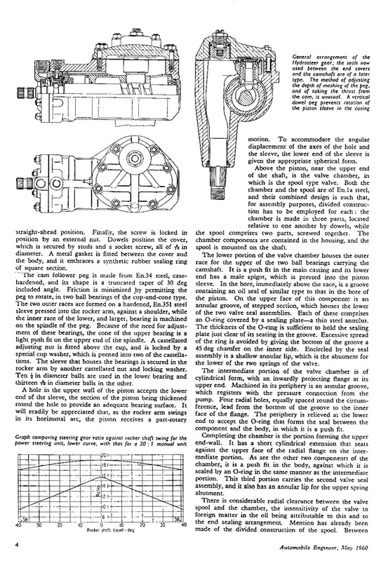
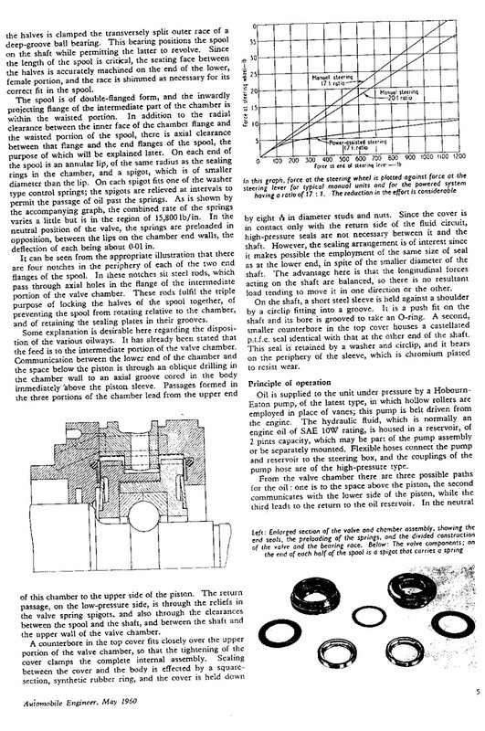
A lock up must have been truly terrifying. A fail safe was designed into the system as described in a very detailed article I have from the "Automobile Engineer" May 1960. The article describes in detail the Hydrosteer Powered Steering for larger cars. Hydrosteer Ltd were based in Luton. England. These were the main design requirements (in precis)
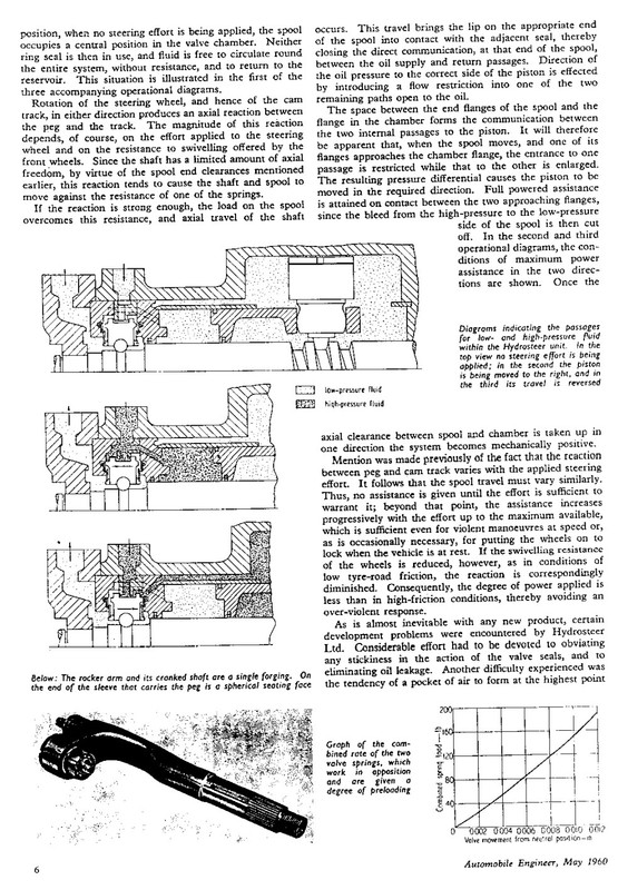
1) It should be fail safe in the event of failure of the power system. The driver should have full control whatever caused the failure.
2) The jamming of the spool type valve because of contamination or foreign matter should be made "virtually impossible"
3) The response of the hydraulic assistance should be a fast as possible.
The article describes, in full detail, the design concept and the technicalities of the engineering and in much greater detail than the WM. The article is meant to be read by professionals. A search on the net might reveal it.
The scope for dangerous errors seems unlimited!
|
|
|
|
Post by enigmas on Feb 19, 2022 12:46:46 GMT
Why not give Eddie a call Martin and discuss what is occurring. It'd be worthwhile just for some feedback.
|
|
|
|
Post by Mike’S-a-loon on Feb 19, 2022 18:40:35 GMT
My steering box, rebuilt by Eddie at Hydrosteer and carefully refitted by Vince is without doubt money well spent. I have 100% confidence in it, and it performs flawlessly.
Your steering locking up, even for a second, is a clear indication that, with the greatest respect to your skills, you should consider having this vital piece of safety equipment professionally sorted out by a specialist who knows these particular units inside out.
|
|
|
|
Post by 3litrekiwi on Feb 19, 2022 20:30:23 GMT
I do agree Mike that this has me baffled at the moment. As I said in my post I will be heading to the local specialist this week. The lock up on the road was only at walking pace but a bit un nerving all the same.
The interesting thing aluded to by Percy is that these are designed to remain safe with no power assistance and this one did this sort of thing previous to me having it apart. Just not a complete lock up but it did get pretty tight. I think this might have contributed to the original steering wheel being so cracked. What I am struggling to understand is how the tightness occurs. At the moment the car turned onto my driveway ok and was turned off. When I attempted to move it inside the wheels wouldn't straighten to go through the door. So I shut the engine off thinking that with no hydraulic pressure the box would free up but it didn't. So the fault must be mechanical. I had put the problem down to the spool being partially full of grease when I dismantled it but sometimes the seemingly obvoius is not the problem.
The worm in this box has no visible damage that I can see but there is a slight tight spot just off straight ahead in operation. When I adjusted it on the bench, I went for a position that this tight spot was just not perceptable, erring on a bit more play than less. I wonder if the rotating peg has a notch in the bearing race, it felt good by hand though.
Thanks Vince, I will give Eddie a call this week but I appreciate that this is his livelihood. He may know of someone over here he can recommend.
I am also going to pull the top off the third box today as if I do need to admit defeat and pass this over to a specialist, I would prefer to give them a reasonably unmolested original to work with. So far the two I have played with have had some pretty rough treatment by previous repairers.
|
|
|
|
Post by 3litrekiwi on Feb 20, 2022 6:39:50 GMT
Managed to get back into the garage, pulled the box again and I can confirm that having done nothing to the spool, it is possible to have a malfunction where the oil doesn't exhaust and the piston is held in the straight ahead position or at least won't allow any movement past straight. This was retained until the end cap came off.
The leakage was due to the rubber gasket getting ejected back into the cavity, presumably by oil pressure. Interestingly the third box I have is stamped 1964 so from a MKII and this seems to have a soft aluminium gasket rather than the steel shim and partial rubber. I don't want to mess with this one so have just re torqued the bolts and swapped the spool end cap as the earlier version doesn't have a dust seal.
Can anyone tell me whether the standard routing for the brake line is around the outside of the steering box? Dropping the brake fluid to get the box out is a pain so next job prior to fitting box #3 is to tuck the brake line in behind.
|
|
|
|
Post by enigmas on Feb 20, 2022 8:32:34 GMT
|
|
|
|
Post by Sam Bee on Feb 20, 2022 12:55:21 GMT
Here is how I routed my new brake pipes, straight along the subframe and reasonably clear of the steering box.
|
|
|
|
Post by 3litrekiwi on Feb 21, 2022 9:11:59 GMT
Thanks Vince, looks like a good bit of bedtime reading. I had a chat to the local guru this morning and he had memories of these back in the day. Not very complementary but we know that. Anyway he reported that he had successfully modded a few in the same way that Eddie has. Funny thing, my first BMW was his wife's prior to us owning it. He offered to give me a bit of a tutorial and if need be sort out a viable one from the two spares. Interestingly and this would only apply to MKIIs and earlier, the gasket arrangement for the top cover was originally aluminium with a rubber bead vulcanised to it. Apparently these delaminated over time and this led to the two piece steel outer with rubber half seal. My dislike of ladles of sealant is something I may have to get over as the only reliable method back in the day was to seal the threads. We will see. I plan on going past a hydraulic shop tomorrow as i like the look of some of the teflon sheeting that is available. Perhaps hydraulic gasketing may have caught up with these old things to provide a solution that doesn't involve a lot of goop.
Its a shame the flanges are not a bit wider as my preferred solution would be to mill an o ring groove around the perifery of both the top and bottom, make a full steel shim and o ring all the bolts. To do this looks like it would involve welding here and there to make room for a groove. A bridge too far at this stage.
|
|
|
|
Post by 3litrekiwi on Feb 21, 2022 9:16:14 GMT
Thanks Sam, looks like the V8 plumbing is a bit different but as you have done, I managed to redo the brake line this evening so that it tucks around the back of the box. Just got to flare the end that connects to the flexible line.
|
|
|
|
Post by johnwp5bcoupe on Feb 21, 2022 19:46:59 GMT
The early boxes had the aluminium spacer with a thin Nitrile gasket this was never vulcanised, the steel spacer was a vast improvement, if you try cutting the gaskets from sheet using a pattern make sure the material is stuck firm (Spray Glue) to some hardboard shiny side, if you don't the the material spreads and wont fit the spacer or the holes! Nitrile sheet is readily available here, can you get it over there?. Sealants/Silicone should never be used it can cause lots of problems.
|
|
|
|
Post by 3litrekiwi on Feb 22, 2022 7:58:00 GMT
Thanks John, I made a gasket by taping the sheet with wide masking tape to stop it stretching and give me something to draw on. I punched all the holes and then cut the outer profile. I would prefer something that enables a full gasket.
|
|
|
|
Post by johnwp5bcoupe on Feb 22, 2022 17:14:41 GMT
No Problem Martin :-) I would think it would be a hard task to get a complete Nitrile washer to seal due to the pressure it would blow the steel gasket makes this possible.
|
|
|
|
Post by 3litrekiwi on Feb 23, 2022 7:13:12 GMT
Hi John, I have drawn the gasket up and will be sending it to a hydraulic seal and gasket firm. Some of the products they have are reinforced Teflon that seems to have very high resistance to extrusion. I agree that no form of rubber is likely to be strong enough.
|
|
|
|
Post by johnwp5bcoupe on Feb 23, 2022 10:28:04 GMT
Hi Martin I have PM'd you
|
|
|
|
Post by 3litrekiwi on Feb 27, 2022 6:12:53 GMT
My saga continues. I fitted my lately aquired third steering box yesterday and although it leaks a wee bit, I now know that the spools in both the previous boxes have faults as I now have nice assistance in both directions with no notchiness or other issues. At idle it is possible to easily spin the steering wheel from lock to lock with the wheels hard down on concrete. This has never been possible before. Interesting that although the working surfaces looked to be in good condition and the disc springs flat with no apparent wear or damage, new o rings throughout, something is amiss with both. Some thorough inspection will be required.
To be assured of the next round being successful my plan is to pull this box again in the next few weeks and fit the internals to my modified case.
I also have some laser cut carbon fibre reinforced top gaskets on the way to see if the top cover can be sealed without resorting to thread sealant etc.
|
|
|
|
Post by enigmas on Feb 27, 2022 10:26:17 GMT
Hi Martin and John,
For the sake of technical curiosity guys, If you are both willing to share some tech info, how critical are the clearances between the spool and the spring plates? What causes the loss in power steering in one particular direction and how is this problem remedied?
PS. I have dismantled a hydrosteer PS box but that was probably 16 or more years ago.
|
|


 (😉)
(😉)