|
|
Post by stan on Nov 9, 2017 15:34:51 GMT
Hi please can you confirm? If the meter is at zero when I am driving its normal? I have a fully charged new battery so presume it doesn't need to top it up much unless I have blower fan wipers headlights etc on as it drops to -ve side?
Whilst I was driving home with it ,( the battery was flat as it had been stood a while I think?) It was into the +ve side presumably charging ?
So when it starts the charge light goes out as expected so it must be working?
I just want to be sure it is actually charging as I drive, before I get the multimeter out and spend hours chasing 52 year old wiring?
Thank you in advance.
|
|
|
|
Post by dmaxwell on Nov 9, 2017 19:40:36 GMT
I found that if the charge meter goes bad, the car dies! That happened to me once and it took me about an hour to figure it out and bypass the meter so I could get home. If the battery is all charged up then the needle should stay in the middle and flicker a bit when using the turn signals or the brake lights come on.
David
California
|
|
|
|
Post by Phil Nottingham on Nov 9, 2017 19:49:37 GMT
It's quite easy and quick to check if the dynamo is charging other than waiting for the battery to go flat. Driving at approx 30 mph just switch on the full lights and the ammeter should BRIEFLY flick a discharge of approx 5A and then go back to where it was. Then switch on the blower and it should do the same. The really big test is to then switch on the wipers. The 30A dynamo should just keep up with all 3 on at the same time but when idling will show a big discharge
|
|
|
|
Post by stan on Nov 9, 2017 20:18:04 GMT
Thank you gents that makes me feel better. It is doing as it should, thank goodness, I thought it would be in the positive all the time if it was charging.
Thats one thing off the worry list onto the next.
Stan
|
|
|
|
Post by djm16 on Nov 10, 2017 9:05:49 GMT
If you really want to know, then put a voltmeter across the battery terminals with the engine running faster enough to charge the battery. You should see between 14.0 and 15.0V.
|
|
|
|
Post by Ken Nelson on Aug 14, 2018 20:06:29 GMT
This weekend I took a 300 mile trip in my P5 Rover Coupe. All went well until half way home I switched on the headlights and the ammeter gauge read -20a or so. When I turned off the headlights it went back to zero. The hi-beams and HL flasher all did the same thing, but everything seemed to be working OK, and the lights did not seem dim, even at idle. I don't think the red ignition light came on, but can't remember completely since my eyes were on the gauge. I have previously fitted a new voltage stabilizer for the instruments, although I do notice that the fuel gauge and temp gauge sometimes vary up or down a bit together-I've just lived with that and it seems stable and OK. Recently I also had the oil pressure light come on during a long trip, but not since. (The oil gauge read "N" throughout though, and I did later replace the sender unit for the light anyway). Now a day after the ammeter reading problem, I started the car up and drove around and the ammeter gauge worked completely normally again. any thoughts please?  |
|
|
|
Post by Phil Nottingham on Aug 14, 2018 21:01:46 GMT
The RB340 dynamo regulator may require servicing - burnt/sticky contacts. The temp gauge and fuel gauge are fed via 10v Voltage Stabiliser and should not be affected. I
If the dynamo regulator is OK you may have an intermittent short or the dynamo brushes are worn/sticking
|
|
|
|
Post by Ken Nelson on Aug 14, 2018 22:33:29 GMT
Thanks Phil, I'll investigate the regulator first.
|
|
|
|
Post by Ken Nelson on Aug 21, 2018 20:48:17 GMT
OK, I'm trying to clean and inspect the voltage regulator but am having trouble removing it from the bulkhead. The 3 retaining screws are free and turn, but won't come all the way out. I assume there may be a nut spinning on the other side (I would assume Rover would have either used sheet metal screws or a captive nut though). Do I need to remove the entire console that the regulator and fuse box are mounted on to hold a nut on the back side of this?? Also, the 20 amp discharge with the headlamps on remains intermittent, but I now have noticed that the red ammeter warning light doesn't come on when discharging, or even when I turn the ignition on before starting the car. Does this perhaps indicate a bad regulator also? |
|
|
|
Post by Ken Nelson on Aug 22, 2018 16:23:32 GMT
See my post above. I'm still trying to remove the voltage regulator, but suspect it is bad and may need replacement. It is a Lucas RB340 regulator, but I see that these come in at least 3 varieties-an 11 amp, 22 amp, and 25 amp version. How do I know which mine is and which to replace it with?  |
|
|
|
Post by Phil Nottingham on Aug 22, 2018 18:16:55 GMT
You need to follow the W/s manual procedure exactly in the same order and do not miss anything out for a start.
Its a 30A version you need but these are apparently rare so if you cannot have it reconditioned (which is the best option) then use the 25A version.
There is little to go wrong with these - far superior to modern solid-state delicate equipment
|
|
|
|
Post by Ken Nelson on Aug 22, 2018 18:42:24 GMT
Thanks Phil. I am still working to remove the regulator from the car to clean everything, but I do have a new unused Lucas RB340 regulator in a box of spares I found that is listed as a "NCB133 control box (0794 354)" that someone wrote on it in pencil "30 amp RB340 series for '66 Jag and '66 Rover P5". I assume this would be the correct 30 amp replacement box if I need it? When you say follow the WM, I assume you mean for testing the box in the car?
|
|
|
|
Post by Phil Nottingham on Aug 23, 2018 17:53:04 GMT
That is the correct regulator but they are basic preset only so MUST be adjusted on the car. The nuts are supposed to be captivated. Fit the replacement side of the old one to see which works best. Swap over ALL the connections including the EARTH (black) Bad earths and other feeds can cause a lot of strange symptoms and voltage/current spikes.
Yes I do mean the manual - random tamperings can be highly dangerous as can burn out the wiring whilst motoring if not set properly
|
|
|
|
Post by Ken Nelson on Aug 23, 2018 18:34:14 GMT
OK Phil, thanks. I'll get to work on them and see what I can find out.
|
|
|
|
Post by Ken Nelson on Sept 4, 2018 22:33:22 GMT
Still investigating the voltage regulator and electrical connections. I've cleaned everything up, but some of the wires at the fuse box have lost their color coding and I'm trying to relabel them. The WSM seems to only show 2 fuses in the diagram for MkIIC P5 Coupe, so I'm not sure about the wire colors on the left side of box (facing car). Picture attached. I think the top left should be Brown, next down should be Red and I don't know about bottom 2 connections. The opposite side of box shows Green and either White (or perhaps Yellow). Can anyone tell me correct colors to clarify please? Thanks Attachments: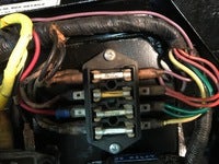
|
|
|
|
Post by Phil Nottingham on Sept 5, 2018 18:17:21 GMT
Look better than ours - I will look. However the wiring is simple and by elimination, the correct ones can be identified, Have you the wiring diagram?
|
|
|
|
Post by Phil Nottingham on Sept 5, 2018 19:50:58 GMT
Clearly overdrive/manual as uses 4th Fuse? Standard Lucas colour code PO's tampering excepted
Left side of the box are all unfused feeds. Right side always via fuse
Fuse 1-2 Brown into Purple (Battery Feed accessories)
Fuse 3-4 White into Green (Ignition Feed accessories)
Fuse 5-6 Red into Red/White (Sidelight circuit for instrument lighting
Fuse 7-8 White from #1 into Yellow (Ignition fed overdrive switch for relay)
Clearly Accss 4 & 6 are transposed which could well explain some of your problems?
|
|
|
|
Post by Ken Nelson on Sept 5, 2018 19:57:13 GMT
Yes, I have the WSM and have explored the extremely fine print further and have finally found the 4 fuses with the numbered connections! Hooray, I can see that it looks like on the right side of the box (facing car) I have the Red/purple wires switched with the Green wires and should switch them around. On the left side of the box I believe top should be Brown, next down should be White, 3rd down should be Red, and bottom should be White again. Then the bottom wire on the right side is actually White/yellow. Perhaps you could check if this is correct for me on your car? ALSO, I did try running the car after cleaning these connections-it ran fine, and the ammeter showed correct reading, but AFTER I shut it off I noticed smoke just starting from the area of the back of the generator. The regulator seemed slightly warm also, but the generator area was the worst. I disconnected the battery for now. Is it possible the generator could be shorting out? (The contacts in the regulator seemed OK-could they be a possible culprit instead) Thanks in advance for advice! |
|
|
|
Post by Ken Nelson on Sept 5, 2018 19:59:28 GMT
Thanks-yes I just read your post and that would agree with my analysis. It does have manual with O/D.
|
|
|
|
Post by Phil Nottingham on Sept 5, 2018 20:40:08 GMT
It may be the cut-out points are sticking and the battery is trying to motor it. Slacken dynamo belt and this will allow the dynamo to spin freely which of course it cannot when the belt is tight. This situation must be rectified as the dynamo windings will burn out. The cut-out voltage may be set too low - adjustment is possible per the manual (follow precisely)
I agree with your colours too except mine has no 4th fuse connections as it is an auto - look on the overdrive or overdrive switch for a Yellow/White cable
|
|
|
|
Post by djm16 on Sept 6, 2018 23:34:12 GMT
Yes that sounds exactly like the cut out contacts are closed. If you take the cover off the regulator, you may find that the varnished copped windings have turned black.
|
|
|
|
Post by Ken Nelson on Sept 7, 2018 23:38:13 GMT
Well, the plot thickens. The regulator coils were not burnt, and after cleaning contacts again the generator no longer got hot. I think it must have been the cut-off points stuck before. However the car still showed 20 amp discharge intermittently with headlamps on so I installed my new Control Box. So far it's working normally. BUT I switched the green and red leads (on right side of fuse box) around as Phil said earlier, and found then my panel lights and parking lights would come on with the ignition and stay on. I also noted that the white "jumper wire" on the left side in WSM diagram goes from terminal 3 to terminal 7; but on my car goes from #5 to #7. If I put it from #3 to #7 my gauges stop working. So it's back again to the Green and Red/purple where I started (Red/purple on #4 and Green on #6) and White jumper from #5 to #7 as before. Everything works OK again, EXCEPT now my O/D won't work! I have no idea what PO may have done, but will gladly leave alone if I can get O/D back again! Any advice on checking OD??
|
|
|
|
Post by Phil Nottingham on Sept 8, 2018 14:39:15 GMT
Someone has messed with the wiring! One of the wires should go to the overdrive relay via the switch - Yellow via the lower ignition only fuse.
Try a direct battery connection(onto purple cable) to this cable bypassing the Ignition. You need not start the engine just put gear lever into 4th and see if the relay/solenoid clicks when column switch is moved.
The wiring on these is incredibly simple but age does not help colour retention nor prevent previous alterations
|
|
|
|
Post by Ken Nelson on Sept 8, 2018 21:13:29 GMT
Thanks-will try tomorrow.
|
|
|
|
Post by Ken Nelson on Sept 11, 2018 19:47:21 GMT
Hi Phil-OK, I connected Purple wire (#2 terminal) to White/yellow (#8 terminal) and put the car in 4th gear (engine off) and I can hear the solenoid click on and off with the OD switch on the column. I get continuity across the bottom fuse (terminal #7 to #8) so fuse and connection seems good. Could something have effected the relay for OD? Any suggestions on how to check that out further? Again, thanks in advance.
|
|


