|
|
Post by eightofthem (Andy) on Sept 1, 2014 18:48:54 GMT
There is a pressure test point on the box which you can tap into, this will tell you if you have line pressure, but you can still have good line pressure with a failed clutch pack or band.
If you intend to drop the valve body out, you can do the air tests again in situ.
|
|
|
|
Post by mspencer100 on Sept 1, 2014 22:48:32 GMT
With low pressure would that indicate bad front pump, Torque converter or VB? I guess it depends on what test fails. I will run the tests and let you know what i find.
Thank you.
|
|
|
|
Post by harvey on Sept 2, 2014 12:27:04 GMT
The pressure point only tells you if the pump is working,(and the pressure it's working at), and you already know that it is, because you have REVERSE, so I wouldn't bother. You could remove the valve block and air test the front clutch to see if you can hear it working. Other than that all you could do is check for the correct fitment of the fluid pipes, and the manual control valve.
|
|
|
|
Post by micmadox on Sept 23, 2014 21:51:51 GMT
Hello All,
May I step in ?
Just as a matter of brief introduction, I will say I have had my P5B Coupé for almost 22 years now, 18 of them on the road ... but for the last 4 as the car has been stopped by its gearbox.
Indeed, second time, but first time 8 years ago one box was changed for one rehauled by a specialist, and car was back within months.
This time I procrastinated, wondering about solutions, until I saw Andy's wonderful job and read Harvey's wise comments.
Then, decision was made, I will rebuid one myself.
As a matter of introduction, I have now dismantled three boxes I had here in France :
- first one, which broke 8 years ago, revealed a seized oil pump ... that was after some sand went into the box (once I will tell you how it happened ...) !
- in the second one, which broke 4 years ago, I found some kind of "sun and planet salad", with teeth all around ... that was the one rebuilt by specialist, which had lasted only 6000 km or so !
- the third one, supposedly rebuilt and ready to go, eventually appeared to be rebuilt ... and not ready to go : manual control valve not properly set with the command, and downshift cable not set at all !
... but probably ready to break soon : oil pump bearing in real bad shape !!!
Hence, I know now that I want to dismantle it completely, valve body, servos and clutch, as I don't want to reassemble subsets that may simply not be safe.
For what I have understood, some special tools and techniques will be required : I have see the one built by Andy, for handling the clutch, but wonder how those for servos look like.
Would anyone have pictures of some ?
To say it, indeed, my dream would be to find those tools and either purchase or rent, but as I understand this might not be possible, seeing them and getting specifications would greatly help.
So, thanks really if some of you can help.
M.
|
|
|
|
Post by harvey on Sept 24, 2014 13:45:04 GMT
For what I have understood, some special tools and techniques will be required : but wonder how those for servos look like. There aren't any special tools required for the servos. To set the front servo you can use a 1/4" spacer, but you can also do it by torqueing it up and backing off the adjuster by 4 complete turns. The only tools that you will require are the installers to refit the pistons back into the clutch drums. |
|
|
|
Post by eightofthem (Andy) on Sept 24, 2014 20:35:36 GMT
Welcome to the forum M. Firstly, well done on having a go yourself, I take my hat off to you. The job may take longer to complete, but you will end up with a better understanding, and a better transmission in the end. If you are stuck for any parts or special tools, Harvey will be only to happy to help you out.  . Good luck. |
|
|
|
Post by mspencer100 on Sept 24, 2014 21:13:27 GMT
The pressure point only tells you if the pump is working,(and the pressure it's working at), and you already know that it is, because you have REVERSE, so I wouldn't bother. You could remove the valve block and air test the front clutch to see if you can hear it working. Other than that all you could do is check for the correct fitment of the fluid pipes, and the manual control valve. Thanks, I have been on another project finishing up a 1968 C10 Pickup, but now I am back ran the pressure test below are the results. Idle Pressure Test:
1. Engine is warm 2. Engine at idle 550RPM 3. Position D: gave me 61 PSI. Correct range is 50-62 PSI 4. Position L: gave me 62 PSI. Correct range is 50-62 PSI 5. Position R: gave me 62 PSI. Correct range is 50-62 PSI So that test looked good. Pressure regulation check:1. Set brake 2. Move to D 3. Run RPM to 1000 4. Correct range is 90-110 PSI 5. At first it was 60 PSI but as I adjusted the throttle cable (at idle) I was able to get it (at 1000 RPM) to sit at 100PSI. 6. I left the throttle cable at that setting. 7. Still no forward movement I see there is a “Stall” test but my book says it’s not a test for my year car so this was not done. I am in the process of pulling the pan to do the air test. Will update you as soon as I am done. Thank you. |
|
|
|
Post by micmadox on Sept 24, 2014 21:35:57 GMT
Thanks Harvey, I think that what I had in mind were these piston installers.
What do they look like ?
My challenge is either to find them, original ones, or try with something similar that I may source here in France ... who knows !
M.
|
|
|
|
Post by micmadox on Sept 24, 2014 22:04:34 GMT
Thanks also for encouraging me, Andy, I think I will need it.
At this point, I have certainly acquired some experience in dismantling the boxes, but I am sure that reassembling one is yet another story !!!
M.
|
|
|
|
Post by enigmas on Sept 24, 2014 23:23:43 GMT
Think about that particular tool and the job it does and if you are reasonably handy you can make one with a bit of improvising. It's not that hard.
|
|
|
|
Post by micmadox on Sept 27, 2014 17:20:56 GMT
Thanks Enigmas, I believe I can understand the origin of your pseudo !  Coming back to the point of these special tools and related techniques ... With some research in the documentation I could procure, I could find : - Rover P5 WS manual refers only to one "inserter", part ref. 601290, for rear clutch, illustration N°40 and nothing else (but for the "spring compressor" Ref.601283 - Ill. N°39), - Daimler 2.5l saloon Service Manual for the BW35 refers to a similar installer for the rear clutch piston, "Service Tool BW41", with in addition another one for the front clutch with a different reference "Service Tool BW42" - there is a quite detailed illustration of BW41 / additionally, there is also an illustration of the spring compressor, reference "Service Tool BW37A", which by the way is different from the Rover one (!). - One "Technical Insight" series of three articles in Practical Classics (Jan-Feb-Mar. 2009) on BW35 rebuild mentions a "Churchill sleeve guide" needed to fit the piston, with a picture. Hence, no real wonder what the installer/inserter(s) have to do, and what their overall shape is. Question is, what they actually are, and their exact dimensions ? As, reading again past conversations on this topic (pages 5-7 of this thread), it looks like even with the proper tool, success is not easy ... So let's put all chances on my side, I'll need it I guess  Well, if someone can help with pictures, and details, really all my gratitude ... M. |
|
|
|
Post by micmadox on Sept 28, 2014 8:18:52 GMT
In the meantime, completing the introduction to my three gearboxes.
First one is a "7FU-26648", with yellow-green tag.
I understand that the guy who sold me the car had swapped it from a 3l MkIII (of which I had many other parts).
This one was on the car from 1991 to 2005, running with me more than 60000 km.
Its end came about two years and 5000 km after it was "internally sanded" ... due to replacing the radiator with a rehauled one.
Not checking what could be in the oil cooler coil was my mistake, as there was sand in there, dry and hard ...
Only too happy to invade the box, as soon as it was bathed with oil !!!
This box has a first series governor, and first series (manual adjustment) front servo.
Its valve block is marked (cast) with a big "1" on upper valve body, similar to the one on Andy's rebuild.
Second one is a "303-6050", with yellow tag.
It came as a replacement to the first one after it broke.
I have no clue which car it was on initially, only said "P5B", as I purchased it from eBay, and then had it "rebuilt" in UK.
Then, ran for about 5 years and 10000 km ... and broke !
Opening evidenced "less teeth sun and planets", and lots of bits all around
This one also has a first series governor, and first series manual front servo.
Its valve block cast shows a big "4".
Third one is a "7FU-12915", with a green tag.
It was sourced from a friend, to whom it had been given as "rebuilt" ...
Still, after seeing how kickdown cable and main manual control valve were "set", I decided to dismantle it.
Once again, a first type governor is there, but this time with the automated adjustment front servo.
And valve block casting is one more different type, with a big "3" marked on the upper valve.
At this point, I am curious of these different combinations, and wondering what the experienced and experts would say of all this ... ?
Knowing that at the end I have to rebuild one box out of the three, would there be a specific advice regarding selection of the parts ?
... on the top of one obvious, which is that I need to select those in best condition !
But is it reasonable to re-assemble parts coming from different boxes ?
Well, looking forward to opinions ...
M.
|
|
|
|
Post by eightofthem (Andy) on Sept 28, 2014 9:05:12 GMT
Here is a good picture of the rear installer, as you can see it is very thin to enable it to fit in side the drum, but it has a large rim that sits on top of the drum to seat it squarely, it is also tapered. 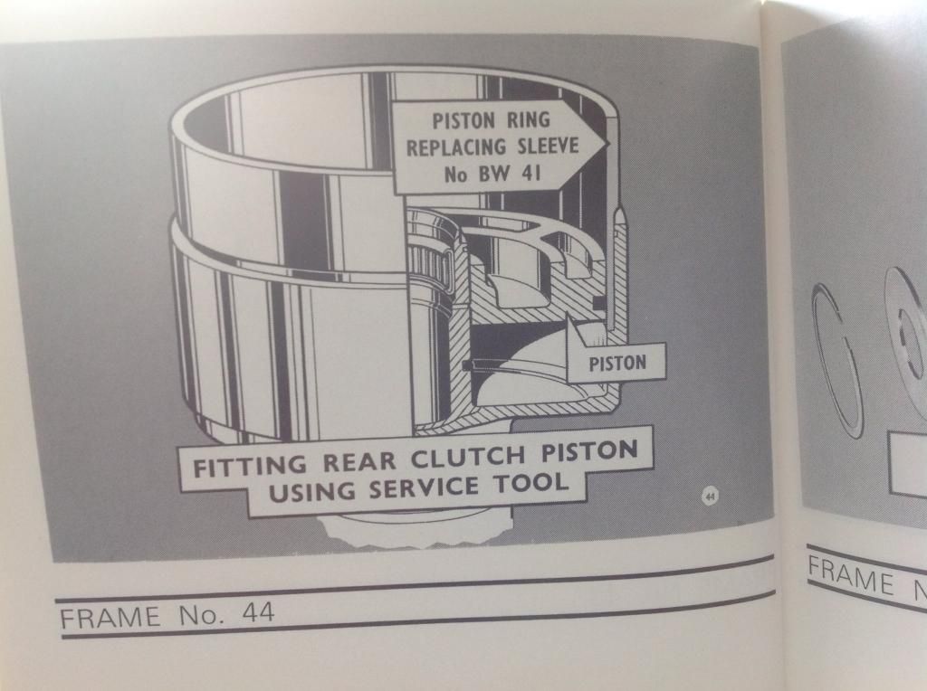 The front installer has a thick wall which is tapered downwards and is chamfered at the piston end. If you get stuck with fitting them, have a chat with Harvey, he will have a solution for you Fair play to him, he did forewarn me of the difficulty in fitting the pistons without the tools, but there is another way as he mentioned. I have tried many methods, some more successful than others, but the correct tool is the way to go, if it were my own personal box, then I would be happy to use the alternative method, but if the box were for someone else, I could not afford to run the risk of damaging the seals and have it fail on them. What I have tried to show in the rebuild is the difficulties that someone will face when building their own unit, and the choices that will have to be made when faced with the lack of the correct service tools. I am afraid the choice is down to the individual on how they wish to proceed, what I posted up here is just a guide, not the gospel. |
|
|
|
Post by micmadox on Sept 29, 2014 19:01:51 GMT
Thanks Andy. The picture I found on the Daimler manual looks very much like the one you have. Realy easy to understand how it works ... although not why it is still so hard to fit the piston ?  Anyway, as I am afraid I may not find this special tool, and the box I have to rebuild is mine, would you describe your alternative techniques ? Most likely I will have to apply one or the other ... M. |
|
|
|
Post by micmadox on Sept 29, 2014 19:16:46 GMT
And following up on the "three boxes - three valve blocks", here are the pictures : "7FU-26648" - marked "1" : <img src="http://staticclub.caradisiac.com/private/1/voiture-ancienne/rover-p5b/photo/hd/657411657/4932951068/rover-p5b-img_4507-7fu-26648-big.jpg" alt=""><br><br>"303-6050" - marked "4" : <img src="http://staticclub.caradisiac.com/private/1/voiture-ancienne/rover-p5b/photo/hd/657411657/4932947fc5/rover-p5b-img_4561-303-6050-big.jpg" alt=""><br><br>"cc" - marked "3" :  Would anyone know about differences between them ? And is it of any importance ? M. |
|
|
|
Post by micmadox on Sept 29, 2014 19:19:27 GMT
Looks like I have missed something about image insertions !  Here is the "7FU-26648" - marked "1" :  |
|
|
|
Post by micmadox on Sept 29, 2014 19:21:35 GMT
And here is the second one, "303-6050" - marked "4" :  |
|
|
|
Post by micmadox on Sept 29, 2014 19:53:17 GMT
One more question : anyone having experienced this type of tool, for the "clutch spring compression" job ?  I ask, as it looks like they can be procured on eBay or Amazon, for reasonable price ... and I have no welding facility, so would like to avoid having to build of one Andy's (clever) type. |
|
|
|
Post by eightofthem (Andy) on Sept 30, 2014 20:16:34 GMT
The important thing to bear in mind when you decide on which valve block you are going to use, is to check that the components within it are what and where they should be, as Harvey has pointed out in the past, these boxes have been apart many times in the past for whatever reason, so it would be prudent to check all the components are correct.
As for the spring compressor, you don't need to weld one, you can make one by using a length of M12 threaded bar, a suitable hard wood base at least 30 mm thick.( such has a kitchen work top off cut )
A small length of steel tube, around 100 mm long, with an internal diameter no greater than 57 mm, ( you will need to cut out a notch to enable the removal of the circlip ) a nice thick steel washer that covers the steel tube outer diameter, and some M12 nuts.
Drill a hole in the center of your wood base, countersink the holes both sides to enable the M12 nuts to sit flush on both sides, and your done.
|
|
|
|
Post by micmadox on Oct 1, 2014 21:40:50 GMT
Thanks a lot, Andy.
I'll try to get a suitable pipe, and see what I can do ...
Regarding valve blocks, I take your advice and will dismantle a first one, as a matter of training ...
Week-end job !
M.
|
|
|
|
Post by micmadox on Oct 6, 2014 22:11:29 GMT
Following on Andy's recommendation : " The important thing to bear in mind when you decide on which valve block you are going to use, is to check that the components within it are what and where they should be, as Harvey has pointed out in the past, these boxes have been apart many times in the past for whatever reason, so it would be prudent to check all the components are correct." ... Well, I thought a little training would do good, hence over the week-end I stripped the valve block (marked "4") of my second box (the "303" one, broken with the "sun and planet teeth salad"). First it appears that the "1-2 shift block" which is there on the box Andy displayed, and on my other two ones, is here replaced by a simple plate. Also one pipe less ... Here is the pic. before opening : ![::)]() M. |
|
|
|
Post by harvey on Oct 7, 2014 14:08:28 GMT
First it appears that the "1-2 shift block" which is there on the box Andy displayed, and on my other two ones, is here replaced by a simple plate. Also one pipe less ... The housing with the "4" on it is the 1-2 & 2-3 shift valve housing, and if the valve next to it isn't there and there's only a flat plate in its place then it isn't a Rover valve block*. Rover boxes always have a valve of some sort, either a D2-D1 valve for the early selector pattern, or a Range Control Valve for the later pattern. If it's a later pattern without a valve and only a flat plate it's from something else, and won't have the second gear start, or the anti-rollback function. IIRC the plate is called a governor line plate. *Well, not a six position Rover box, the 5 position ones do though. |
|
|
|
Post by micmadox on Oct 7, 2014 21:12:51 GMT
Thanks for the clarification, Harvey. Well, years ago I had purchased this box through eBay, in UK, and had it "rebuilt" by a specialist there, then shipped to be installed. Replacing the previous box of my P5B, which had eventually broken, after being "sanded" ! Trying again to insert the pic where this plate can be seen :  |
|
|
|
Post by micmadox on Oct 7, 2014 21:14:13 GMT
And now the same, opened :  |
|
|
|
Post by micmadox on Oct 7, 2014 21:25:50 GMT
For the rest, when dismantling the other components of the valve block, all looked very much the same as the one stripped by Andy. "Upper valve body" :   |
|


 .
.


