|
|
Post by enigmas on Mar 5, 2015 3:01:25 GMT
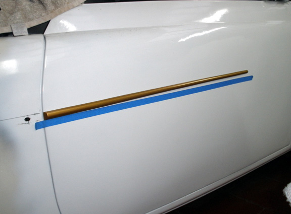
(DJM16) Gold plating the spears is very low on my priority list but they will be gold in colour.  Thanks for the offer of the tools Warwick, but I have enough equipment to sort this out. It's only an irritating weep where the top tank is soldered to the radiator matrix. Considering it's an original 1960s radiator it's endured amazingly well. As for measuring the piston volume that turned into an amazing saga. Anthony, the first contact somehow thought I wanted to buy some high compression pistons from him and then when he realized I only wanted to measure an old 8.13 piston got irritated and told me he couldn't spend all this time fussing around. When I stated that I would do it myself and that this was the first time I had spoken to him, he grudgingly gave me the contact details of the guy who he had dismantled the engine with. I later contacted his mate (a self employed LPG fitter) and arranged a date and time to measure the piston. It was arranged for yesterday at 6pm. It was about 1.5 hrs drive through peak hour traffic. I arrived about 20 mins early. At 6pm I knocked on the door to be greeted by a young school girl who I presumed was his daughter. I asked if he was home and was informed that he had gone out earlier and that he'd be home later...some time? I left and phoned him from my car. He said he was at his brother's (at a distant suburb) and that he was instructing him how to use a shotgun! I stated that we'd arranged to meet at 6pm. He said, I thought it was for Thursday. (I had written the time and date on a scrap of paper at my daughter's place during the call...so I could now verify the details) I asked if there was anyone at home who would allow me to measure the piston. I said I was with my wife. He told me no-one was home...so I left it at that. Good News! None of this info seems to exist anywhere, but then I recalled Dave Manning at Rover Centre in Skye. He works from a large private property (an old farm) and is somewhat taciturn, but very knowledgeable. I gave him a call, he said, "hang on." He got his little black book and gave me the volumes...and said, "do you need any others!" How good is that. |
|
|
|
Post by Warwick on Mar 6, 2015 2:37:26 GMT
Sorry to hear that Vince. That's very odd. Sorry you got messed around.
Not sure what was going on. I've been buying Range Rover parts (new and 2nd hand) from Anthony and his wife Bev for years. I've even been up there to collect bigger parts. They're always friendly and very helpful. When I raised the matter with him, I explained exactly what you were looking for and what you wanted to do, and he made the offer; including that I should get you to ring him. I even gave him your name. He must have initially thought you were someone else.
|
|
|
|
Post by enigmas on Mar 6, 2015 4:21:11 GMT
Warwick, it all worked out well in the end. I spoke to his wife initially and she was very friendly. He must have being having a bad day. Thanks for your efforts though.
|
|
|
|
Post by enigmas on Mar 19, 2015 6:54:07 GMT
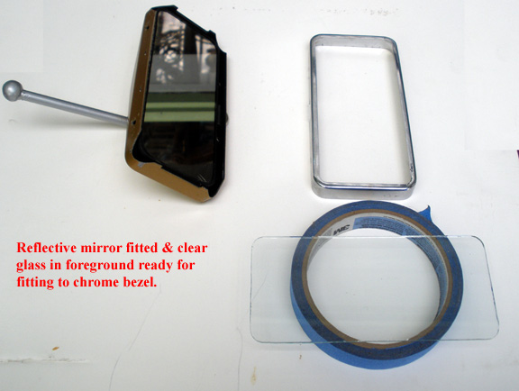
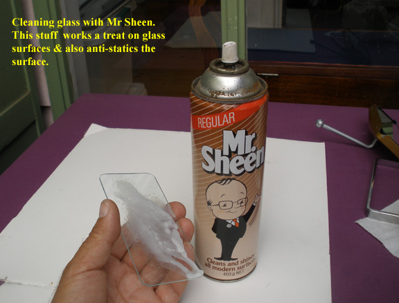
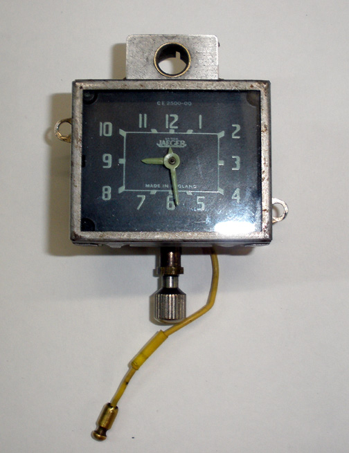
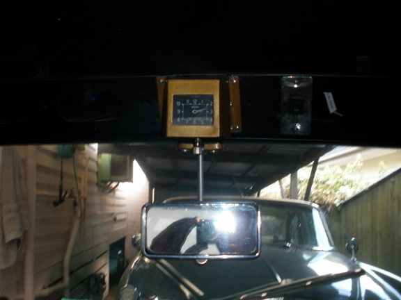
Coupe Update: 05/03/15. Magnette Interior roof mounted ClockI've spent the last few days dismantling and repairing the clock and its mechanism for the Magnette. Fortunately I had removed it and put it aside many moons ago prior to the fire damage, otherwise none of this would have been possible. Interestingly all that was required (to get it working) was a thorough clean, de-dust, and the resoldering of the live wire to it's terminal. The clock is not polarity sensitive (Michael) so will run which ever way you want to feed power to it. The only issue that I could really see with the mechanism, was that the small lever on the back face (for speeding and retarding it) was seized. Adding a few drops of penetrene and gently 'working it', freed it up. There's the world's tiniest screw on this lever, so be very careful before removing it to undo this screw. If you do damage the screw it can still be levered off with care. In some ways this little lever is quite redundant as this mechanism can be 'turned' by directly accessing the tiny slotted screw head in the centre of the post. This is probably the safest way to advance or slow down the clock mechanism. I let the clock run for a couple of days and fiddled with the advance and retard on it attempting to get it to keep some semblance of accurate time. I think this is a more hit and miss affair. The longer it ran the noisier it seemed to become...probably relishing the power fed into it after all the decades of inactivity. It does sound a bit like a bag of bolts but I suppose that is the charm. To start the clock mechanism once power is supplied, simply push 'in/upwards' on the knurled post at the bottom, where the time is altered/selected. 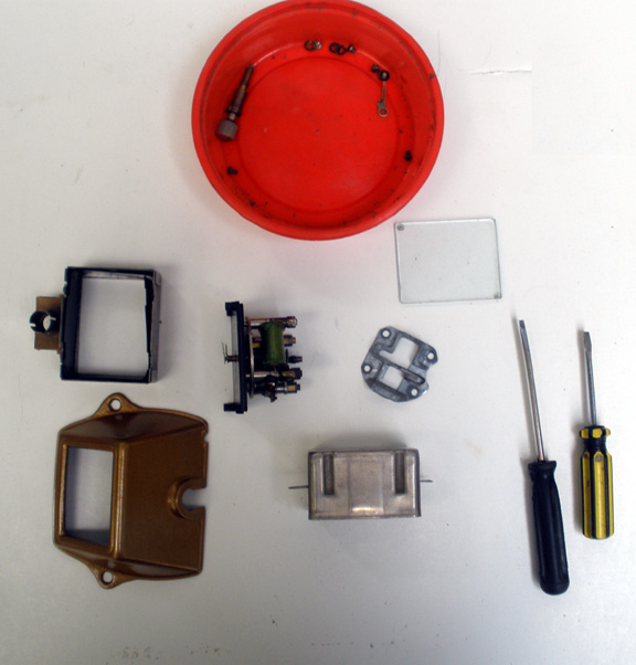  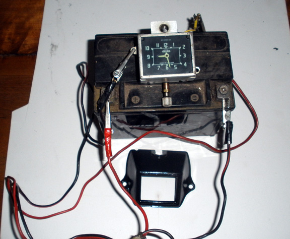 Here are a couple of useful links:www.magnette.british-cars.de/tech-tips/restoration/interior/468-repairing-the-magnette-clock?highlight=YToxOntpOjA7czo1OiJjbG9jayI7fQ==www.clocks4classics.com/uploads/1/2/9/8/12988821/clockkitfittinginstructions__v7.pdf Here are a couple of useful links:www.magnette.british-cars.de/tech-tips/restoration/interior/468-repairing-the-magnette-clock?highlight=YToxOntpOjA7czo1OiJjbG9jayI7fQ==www.clocks4classics.com/uploads/1/2/9/8/12988821/clockkitfittinginstructions__v7.pdf* Turn up the sound...and here's a nice little video of the clock in action! MG Magnette ZB Working Interior Clock
|
|
|
|
Post by johnwp5bcoupe on Mar 19, 2015 9:01:22 GMT
That's the sort of little jobs I enjoy doing Vince well done  The two links don't work Vince the video on is ok! |
|
|
|
Post by enigmas on Mar 19, 2015 9:42:03 GMT
Both links are working now John. (It's always nice when a repair like this works. The clock will be more for show than anything else...including it's own cut off switch so the mechanism doesn't wear any more than necessary. After nearly 70 yrs I think it's doing alright.)
|
|
|
|
Post by enigmas on Mar 21, 2015 11:42:58 GMT
|
|
|
|
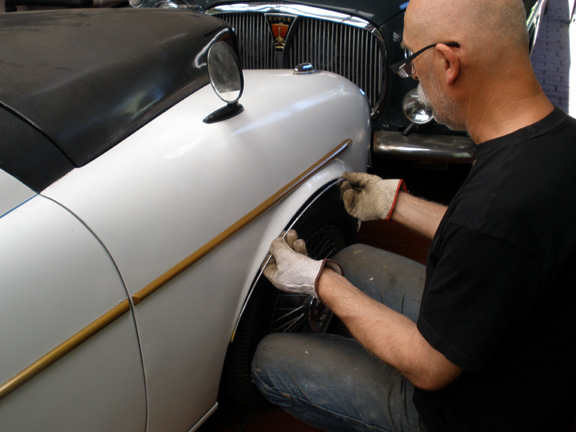
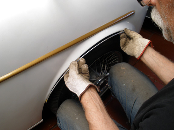
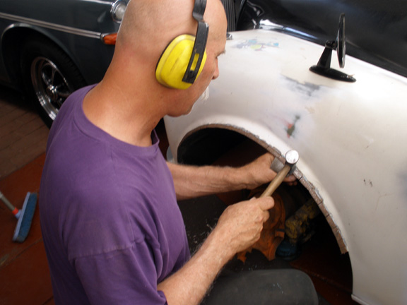
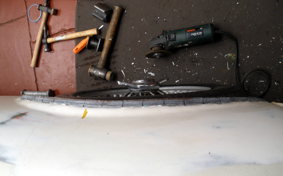
Post by enigmas on Apr 20, 2015 8:52:10 GMT
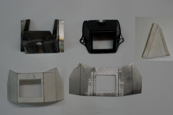
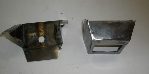
Glove Box Lid & Trans Tunnel Modification 19.04.15 Since fitting the windscreen, I've wanted to finalize the completed dashboard and instrument array. Simply to fit it and be done with it. Fitting the complete wiper mechanism back in place has tended to slow this, as I want to ensure it all functions correctly before it's buttoned up. This car has had 3 different transmission assemblies since I've owned it, so the trans tunnel has been massaged several times. I wasn't really happy with access the way it was, to the gear lever and the various switches that control the reverse light and the overdrive lockout. I've redesigned a number of features on the car to ease access for either servicing or removal. This is just one of them. Whilst I've been doing this, I also refinished the glove box lid by adding a used rear boot emblem to the face of the lid. I had to bend it to match the curvature of the lid and then drill some small locating holes to position it correctly. This took quite a while. 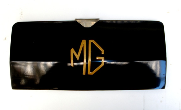 The following images relate to the trans tunnel cover. When I was initially opening it up a bit I accidently cut a couple of wires on the loom (with my trusty and lethal angle grinder.) A real pain! Fortunately I had a Jag wiring loom plug handy and wired this in. So now I can remove the rear half of the loom if I want to (I never will!) 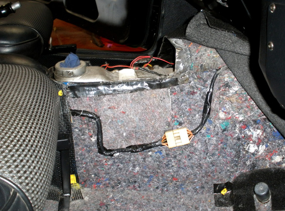 The next image shows the section of tunnel removed to ease access to one of the switches on the side of the gearbox. 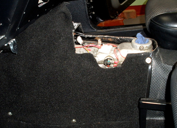 This is the cardboard template used as a pattern. 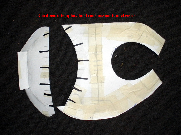 The following 2 images are the trans cover in metal (but not yet welded together. There are 2 pieces.) Although what you see looks like cardboard, it's not. I used a white, mild steel panel from a dishwasher as the steel is a very thin gauge and easy to shape/form. 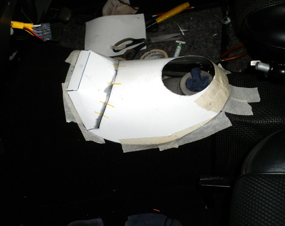 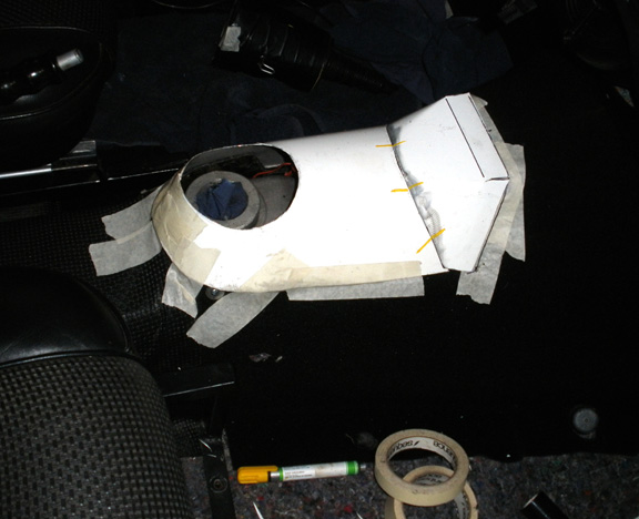 There's still a bit of tweaking required yet, but it's getting there. Next day’s effort: More Trans Tunnel Cover Construction Here are some more pictures of the cover being fabricated. I don't believe there's a need for text as the pictures tell the lot. It's not quite finished yet, as I still want to reinforce the perimeter with a internal band of metal and the gearstick opening with a similar band for the gearstick boot retaining plate (still to be fabricated.) I'm pleased with it though as it fits the tunnel very snugly. 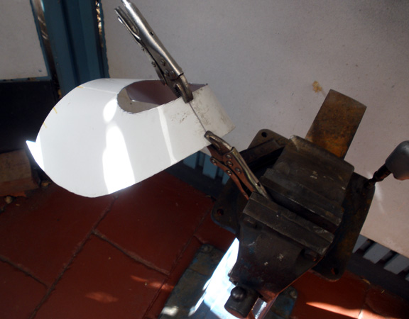       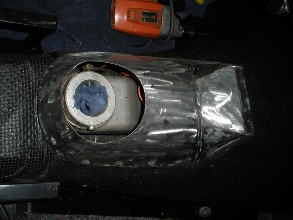
|
|
|
|
Post by enigmas on Apr 23, 2015 7:13:30 GMT
|
|
|
|
Post by enigmas on Apr 28, 2015 6:33:58 GMT
Coupe Update: 28/04/15. Trans Tunnel Cover Construction._Part 3 Here's the final update on the trans tunnel cover and the gearstick boot surround. I'm certainly no upholsterer/machinist but my wife does possess a large singer commercial sewing machine inherited from her mother (fitted with what looks to be a large quarter HP electric motor.) I had some scraps of very soft and pliable black leather and thought I'd give it a go. So here's the finished result. As for the door cards...I won't push my luck, so the covering on these will be done professionally. 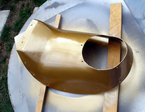 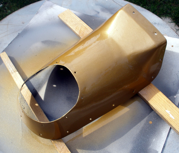   Here's the sewing machine.  and as an aside this is the pink wiring loom in the Magnette... (I'm at a stage where the dash and instrument panel can be fitted back permanently. A couple of days ago I thought I'd plug the instrument panel back in and check the circuits and found that the brake lights no longer functioned. B****r! After a lot of tracing and diagnostic work I unravelled the loom and found that a soldered joint had separated. The open circuit was hidden under a shrink tube sleeve. Tedious and annoying, but better now than when the interior is totally buttoned up!) 
|
|
|
|
Post by enigmas on May 10, 2015 13:57:00 GMT
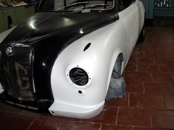
Coupe Update: 10/05/15. Fitting the Dashboard & Locating Wiring Gremlins For quite some time now I've been wanting to refit the complete dash assembly and be done with it. Unfortunately, harking back to an earlier point in the rebuild I needed to replace the complete interior section of the wiring loom, as it was virtually all destroyed in the fire that caused the overall damage to the car. This wasn't necessarily a big deal, but it was time consuming as my self designed custom loom essentially consists of one to two colours of wire, making the tracing of circuits a little bit more arduous. Given that I did most of the rewiring 3 years ago and then subsequently rebuilt the dashboard layout, there was bound to be some gremlins. It took about 3 - 4 days to sort this problem with some down time to let my brain absorb some of the cross circuits that I had inadvertently wired in whilst replacing new for old connectors, etc. Fortunately all of the issues were focused on the DS headlights, parker and indicator. It's very easy when nothing is marked to use an incorrect head light terminal (1 of 3 pins as a ground//earth) This caused some earthing feed back through the circuits and some strange behaviour with a parking light that also wanted to operate as an indicator. Truth be known, it was purely human error, mine, as when often faced with a lot of spaghetti (bundles of wires) it's very easy to wire in an incorrect circuit during a lapse in concentration. Consequently I prefer doing the jobs when the grandchildren are else where! Anyway it's all sorted and every switch and circuit does only what it's supposed to do. As can be seen from the under bonnet photos, I initially bind the loom with blue masking tape approximately every 100mm, adjust the wire lengths, check the circuits and then finally tape the whole loom with black PVC tape. Here are a few pictures of the completed dash layout, some engine bay pix of the essentially pink wiring loom and a shot of the car from the front with the tripod headlights, parkers (on top of the mudguards) and indicators fitted. If anyone is wondering, I've drawn up specific circuit diagrams for most of the electrical system and any complex circuits.  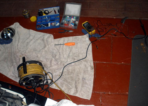 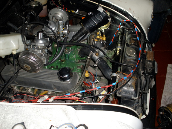  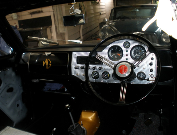 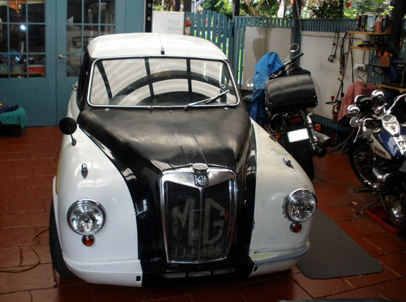
|
|
|
|
Post by johnwp5bcoupe on May 10, 2015 14:25:04 GMT
Great work Vince as usual Is the green manifold a salute to the old lump When is blast off? |
|
|
|
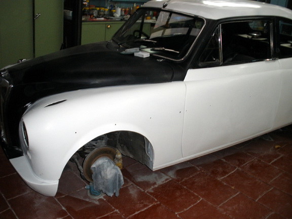
Post by enigmas on May 10, 2015 23:56:49 GMT
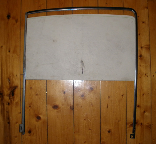
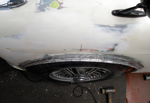
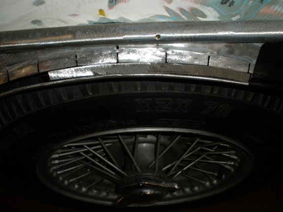
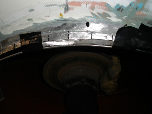
I painted the engine green 20 odd years ago with some industrial paint suited to this application John. MG engines are traditionally painted red, not a colour I particularly like for an engine...a dark maroon perhaps would be suitable. As for blast off, that's still some time off although the car is now fully functional. I still need to fit/manufacture the side windows and alter/construct the window mechanisms for these. There's also the PS mudguard flare that needs to be widened about an inch to match the other guard. Finally I also want to remove the engine trans combo for a tidy and freshen up of the engine bay.  |
|
|
|
Post by johnwp5bcoupe on May 11, 2015 5:43:26 GMT
I painted the engine green 20 odd years ago with some industrial paint suited to this application John. MG engines are traditionally painted red, not a colour I particularly like for an engine...a dark maroon perhaps would be suitable. As for blast off, that's still some time off although the car is now fully functional. I still need to fit/manufacture the side windows and alter/construct the window mechanisms for these. There's also the PS mudguard flare that needs to be widened about an inch to match the other guard. Finally I also want to remove the engine trans combo for a tidy and freshen up of the engine bay. Glad you still have a bit to do Vince otherwise you would only get bored |
|
|
|
Post by enigmas on May 11, 2015 8:11:46 GMT
I suppose that's who l am John. I don't like the word "retirement". It's one of those loaded words that conjures up a lack of passion or commitment to pursuing anything requiring energy or exertion. No, I just stopped working for a boss and pursuing someone else's agenda (no more '3 bags full' sir/ma'am) None of us are immortal and working for the 'man' until my second last breath doesn't make much sense to me! But that's enough of that. |
|
|
|
Post by enigmas on May 24, 2015 12:36:18 GMT
|
|
|
|
Post by petervdvelde on May 26, 2015 21:00:08 GMT
Nice fabrication Vince! I always thought Jaeger was a German compagny but your clock states it was made in the UK.
Peter
|
|
|
|
Post by Warwick on May 27, 2015 2:44:53 GMT
Nice fabrication Vince! I always thought Jaeger was a German compagny but your clock states it was made in the UK. Peter French, with a UK factory. |
|
|
|
Post by enigmas on Nov 2, 2015 13:04:02 GMT
|
|
|
|
Post by enigmas on Dec 15, 2015 21:19:09 GMT
|
|
|
|
Post by djm16 on Dec 15, 2015 23:18:20 GMT
Wonderful work BTW.
A small suggestion about the clock. I am glad you have the original innards workign again. You may know this already, but others reading might well not. The clock I believe has a contact for the coil that is attached to the escapement wheel. A make / break cycle occurs with each tick. Each tick therefore arcs away a small ammount of the fairly fragile contacts. They can be made to last much longer by:
1) adding a shunt diode across the coil, a tiny LED will do
OR
2) using the contacts to operate a FET switch to energise the coil (and a shunt diode / LED to prevent a back EMF from the coil from frying the FET).
Option 2 will rescue a clock that has knackered contacts that will not suport a current great enough to energise the coil but can still support the few micro-amps needed to switch a FET.
Booth these mods of course make the clock polarity sensitive. However if the clock can be electrically isolated, then power can be supplied via a full wave bridge rectifier which will protect the clock if and when the battery is switched.
|
|
|
|
Post by enigmas on Dec 16, 2015 1:20:15 GMT
Thanks for the feedback on the clock mechanism, but it suffices with a on/off switch beside it. It works but sounds like a can of loose nuts and bolts when operating. Very amusing. Time keeping is not a strong feature either. Primarily it's there for appearance, as it's an original period feature of the car.
|
|
|
|
Post by enigmas on Jan 3, 2016 12:46:49 GMT
|
|
|
|
Post by p5bdownunder on Jan 3, 2016 15:44:41 GMT
More great work, Vince. Well done mate. Nearly there...! |
|
|
|
Post by enigmas on Jan 4, 2016 2:48:46 GMT
Thanks Stu, (and John and Owen on the quiet  ) How about giving us a report on how your car's handling the heat in WA Stu? ...and Owen that 'interesting' coupe of yours is definitely worthy of comment. How's it been since the extensive rebuild? Happy new year boys. |
|


 )
)