|
|
Post by enigmas on Aug 29, 2019 8:26:08 GMT
I've been putting some time into my ZB Magnette Coupe project of late and can see an end to the more time consuming elements of the project. So here's an update that includes: Part 1. An upgrade to the small thermo fan I cobbled up years ago and... Part 2. Fabricating a 'Nudge/Fog Light Bar'for the front of the Magnette. Rather than write a detailed outline the photos below should tell the story. Thermo Fan UpgradeSmall fan in place. 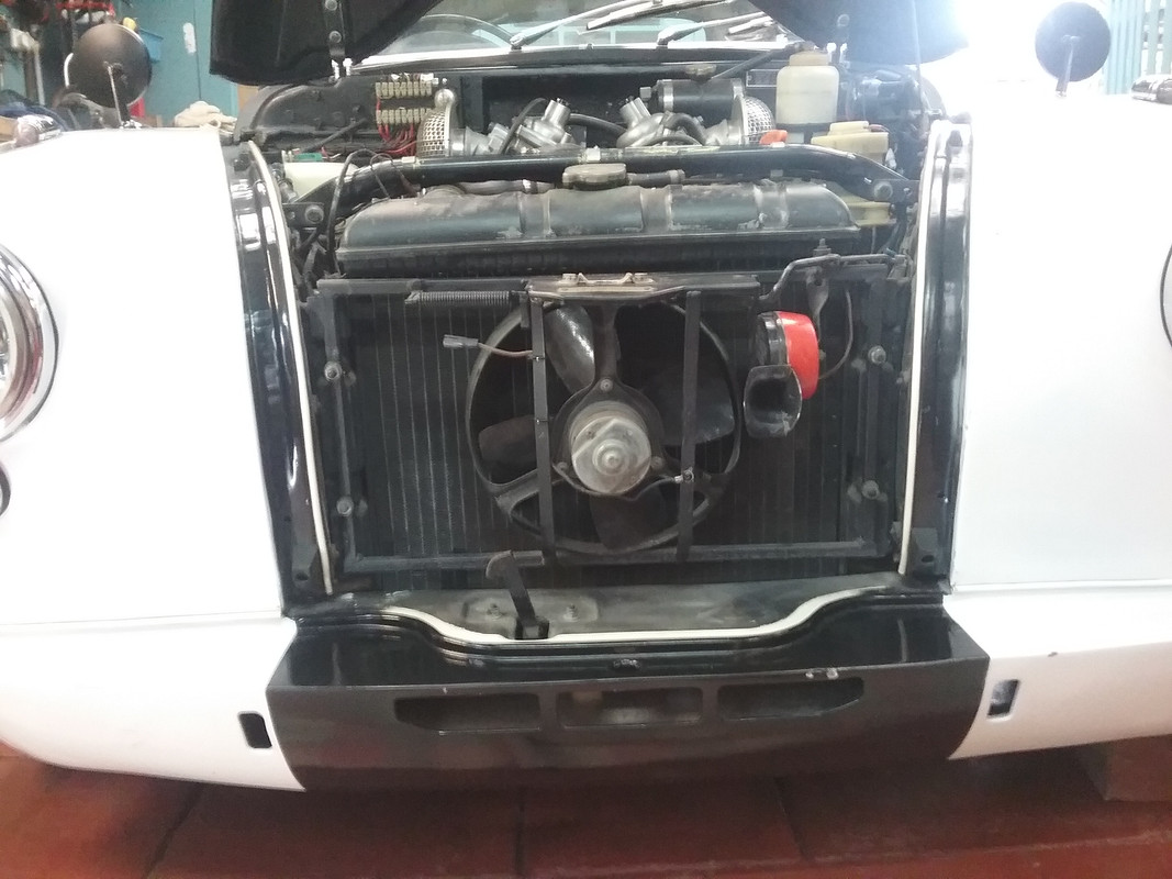 Mercedes Benz fan 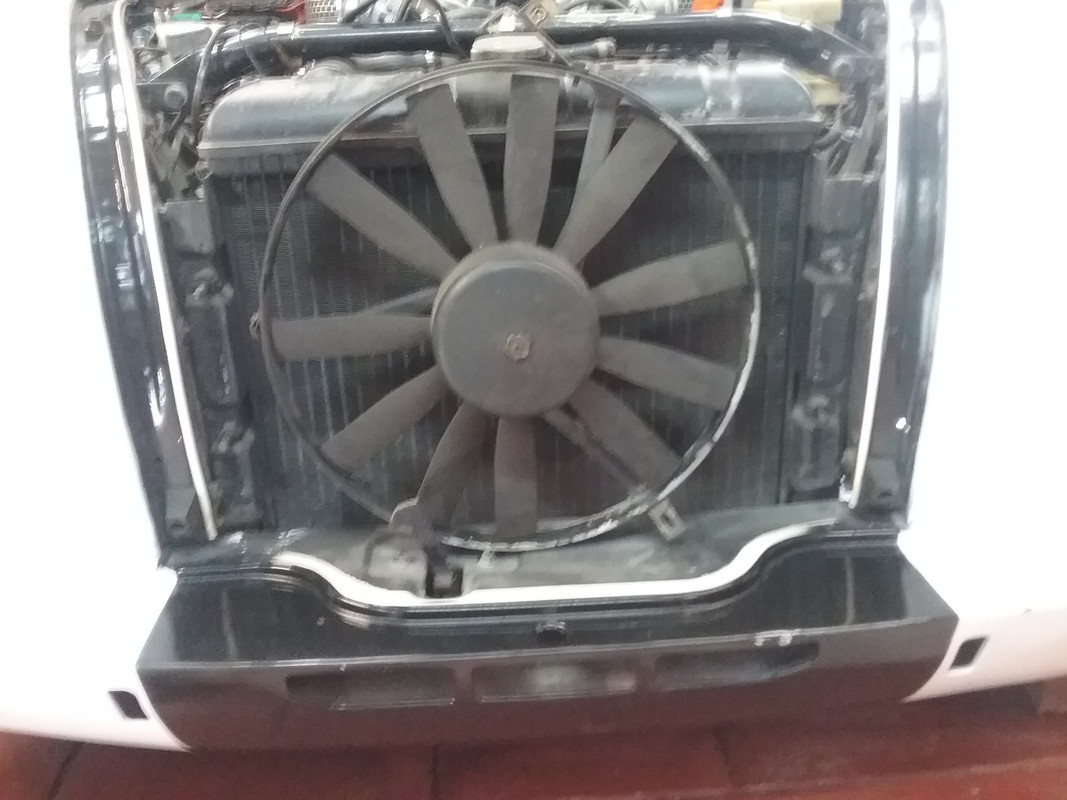 Refabricating combined fan support & Bonnet locking mechanism brace. 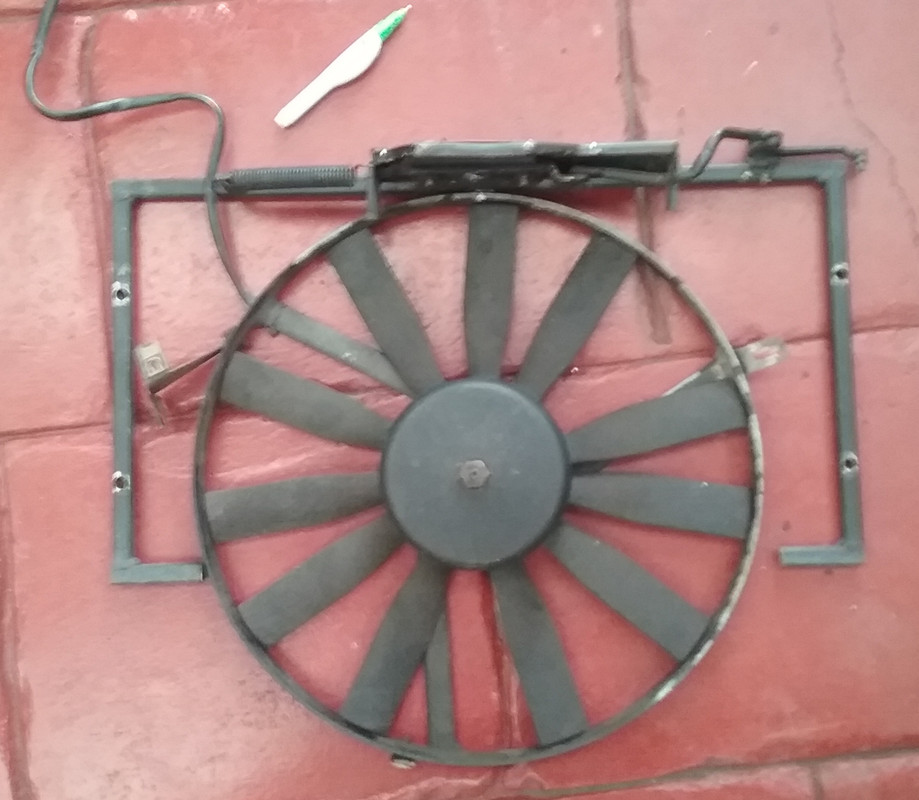 Trial fitting 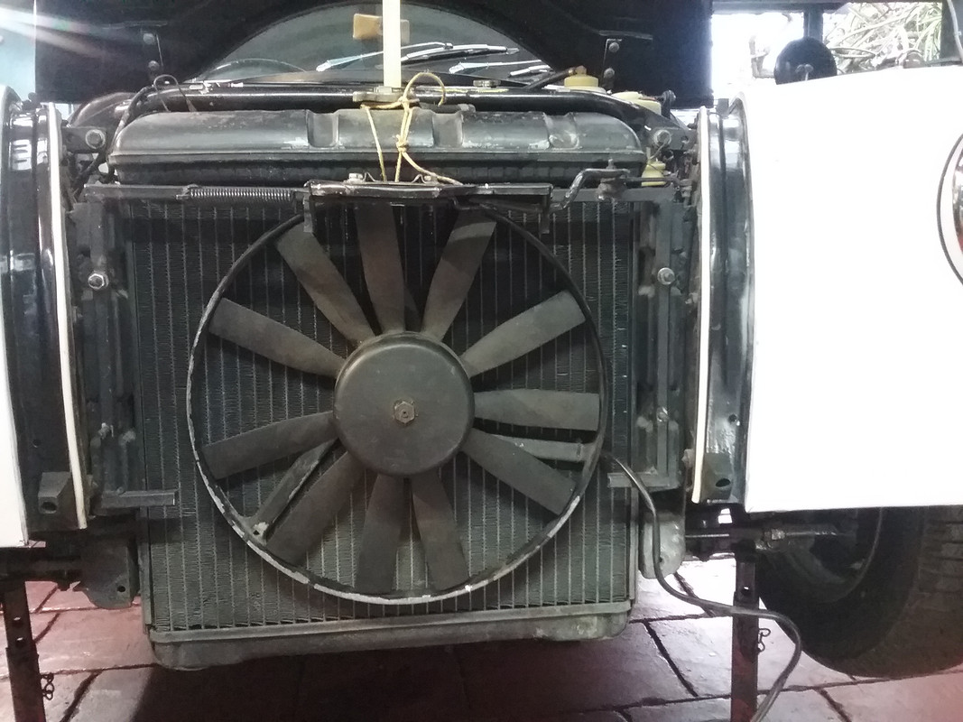 Rejigged support 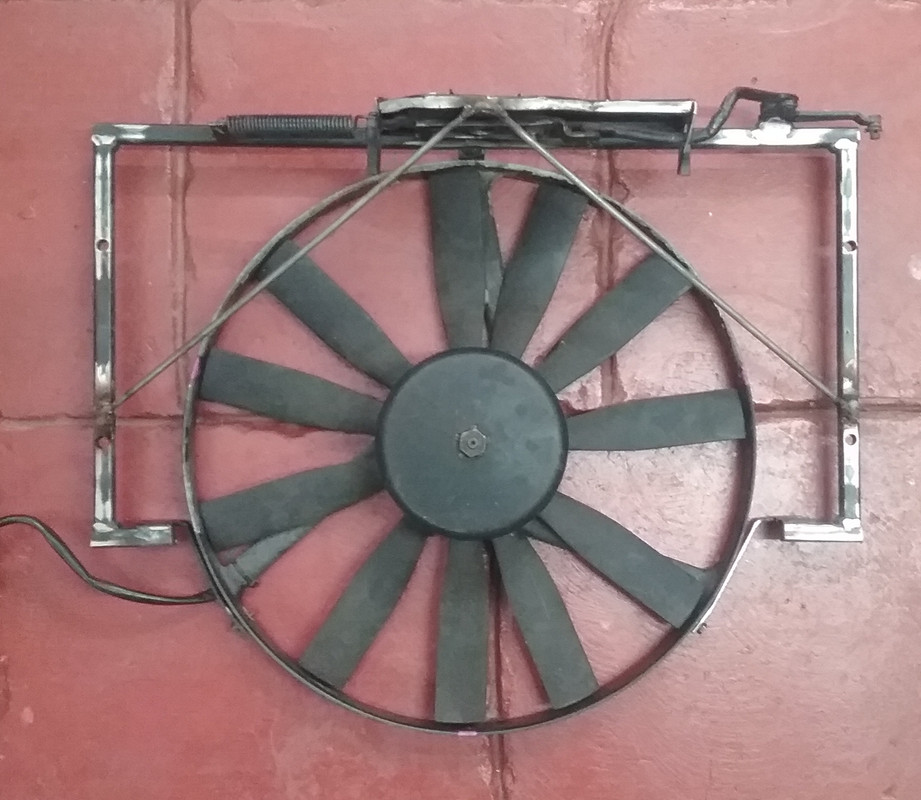 Pieces ready to fit 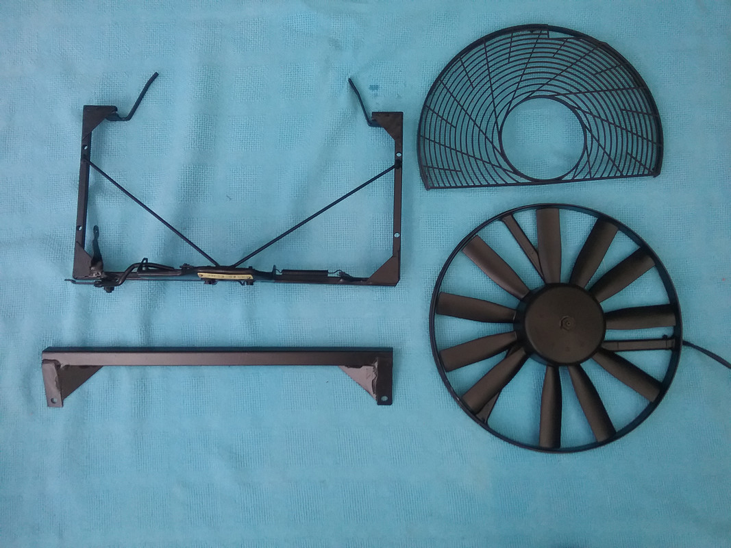 Completed. 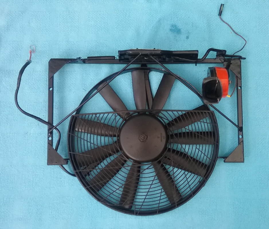 Fitted to car 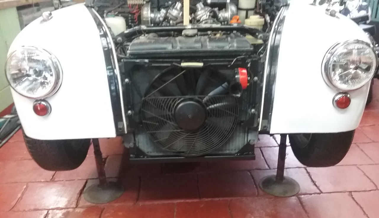 Modifying front valance for fan clearance 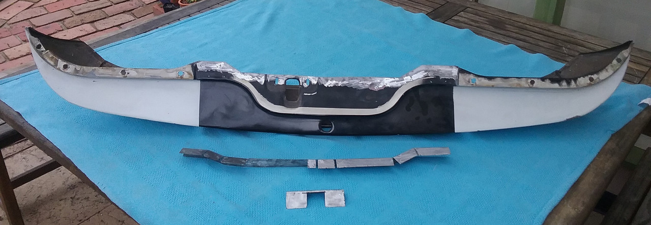 Valance modified and reconstructed 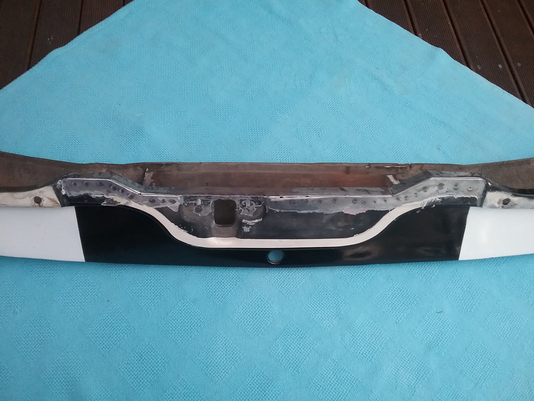 Clearance available 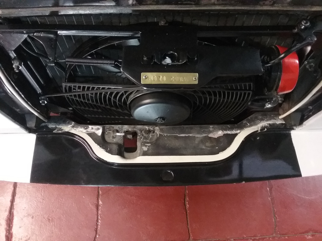 Larger thermo fan in place and finalised. 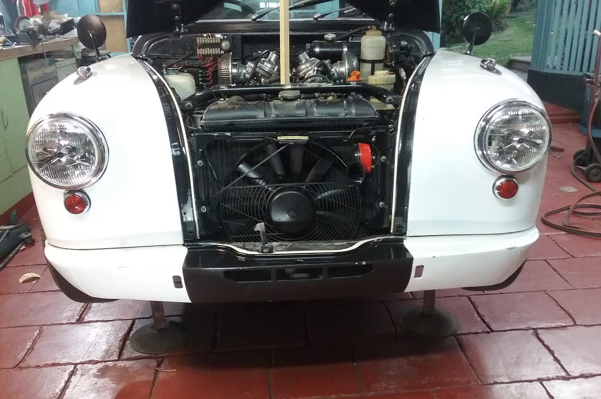 Next post... Nudge/Fog Light Bar fabrication |
|
|
|
Post by enigmas on Aug 29, 2019 8:47:53 GMT
Nudge/Fog Light Bar fabricationDuring a morning walk around my neighbourhood several months ago I found a useful piece of hard garbage that I thought I could put to use at some stage. Here's the item...a set of chrome legs for a kitchen table. When sectioned they were found to be of a very thick gauge steel tube...ideal for my project. 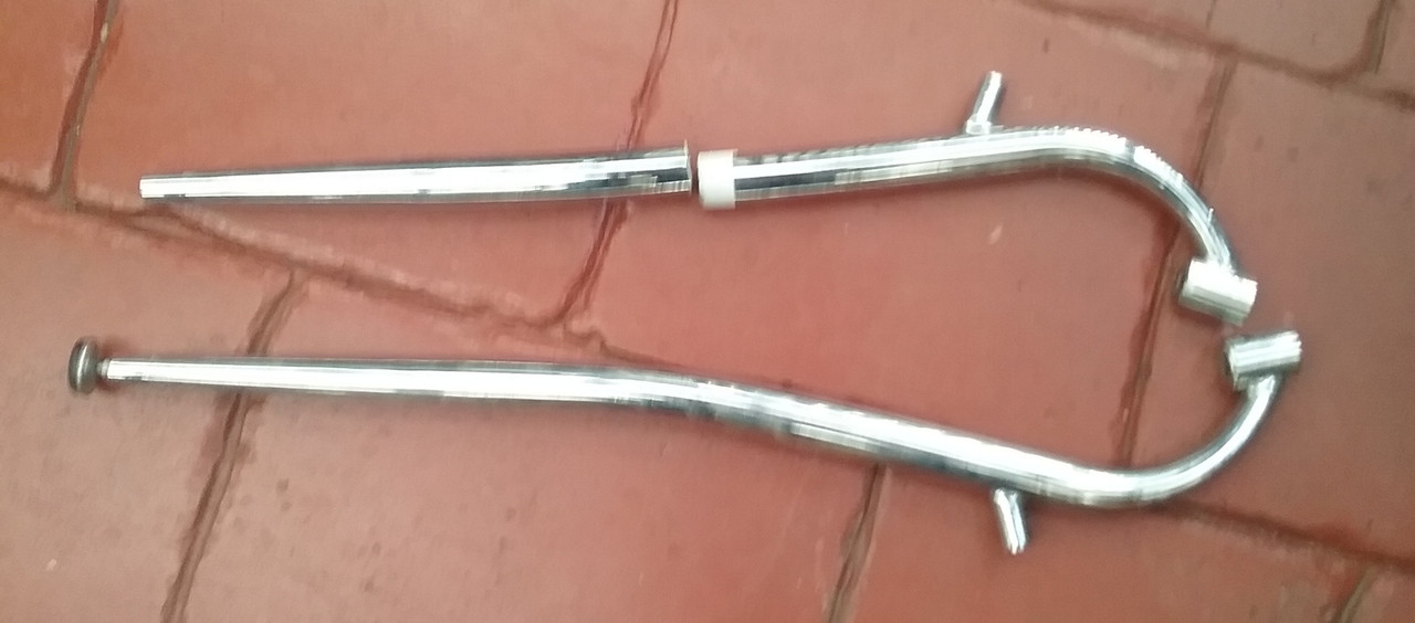 I also had some bumper irons left over from the aircon front bumper and driving light mods to my MK3 P5 coupe. The steel proved useful for fabricating the Nudge Bar supports... 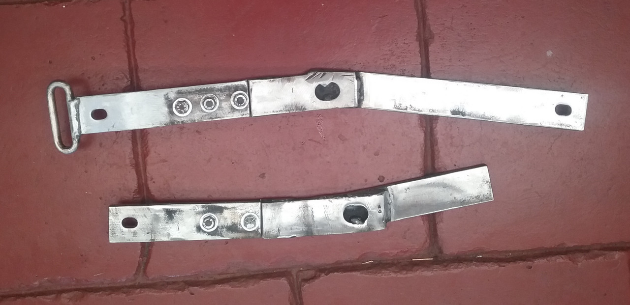 which were welded to the chassis extensions on the Magnette here (DS) and... 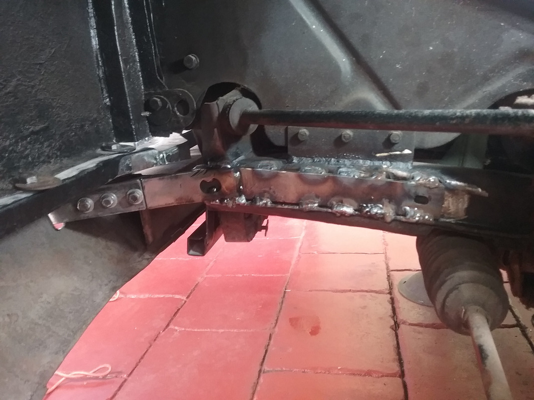 here PS. 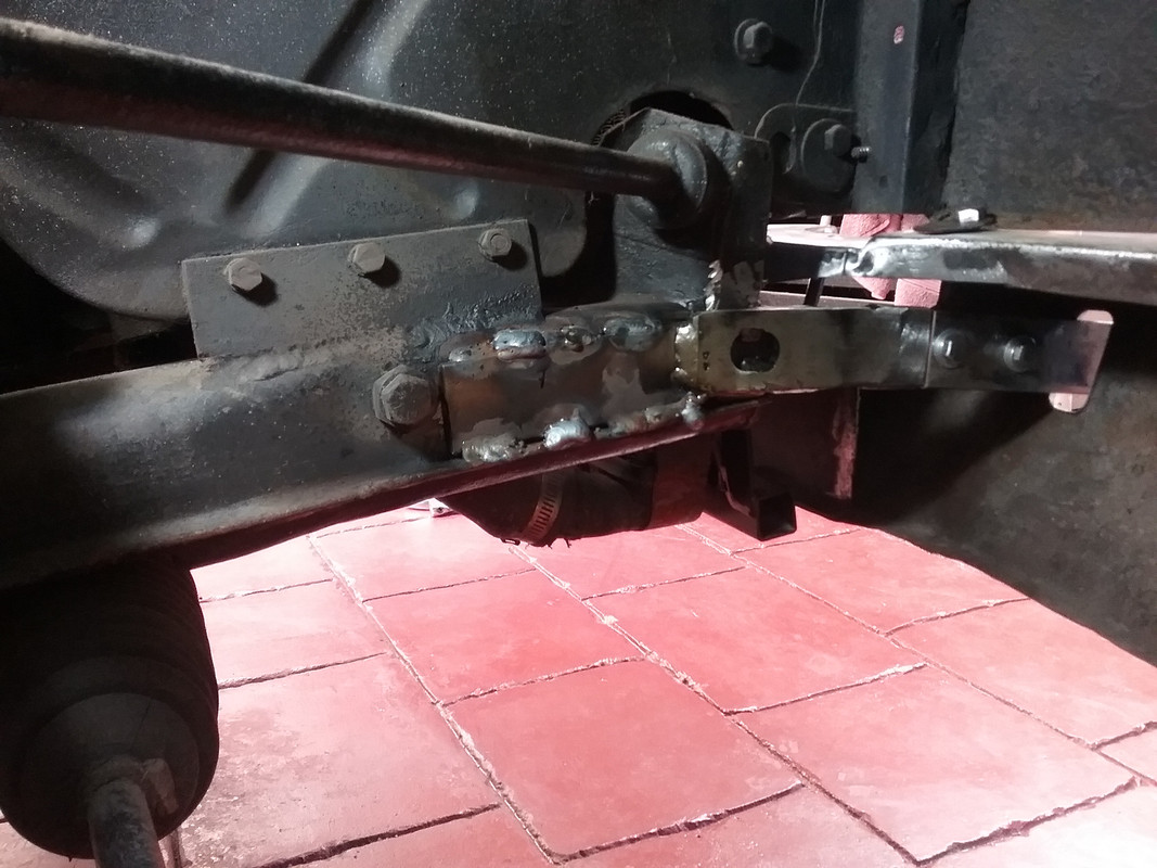 They were then painted... 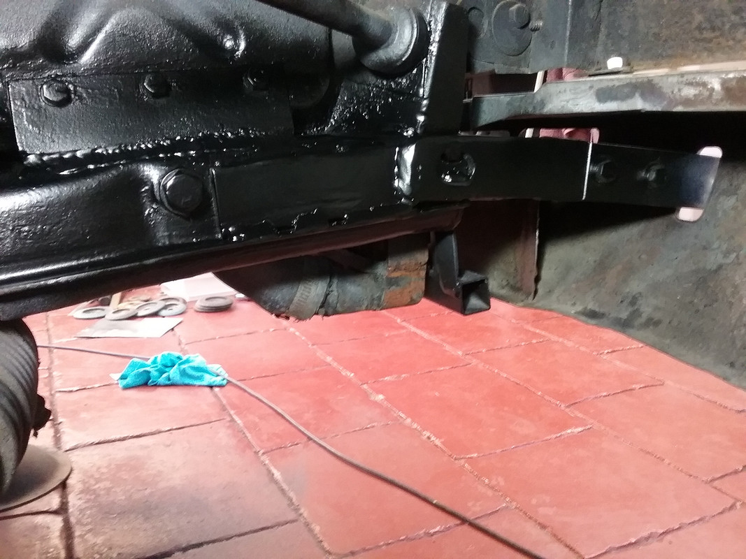 and fitted through the openings in the front valance... 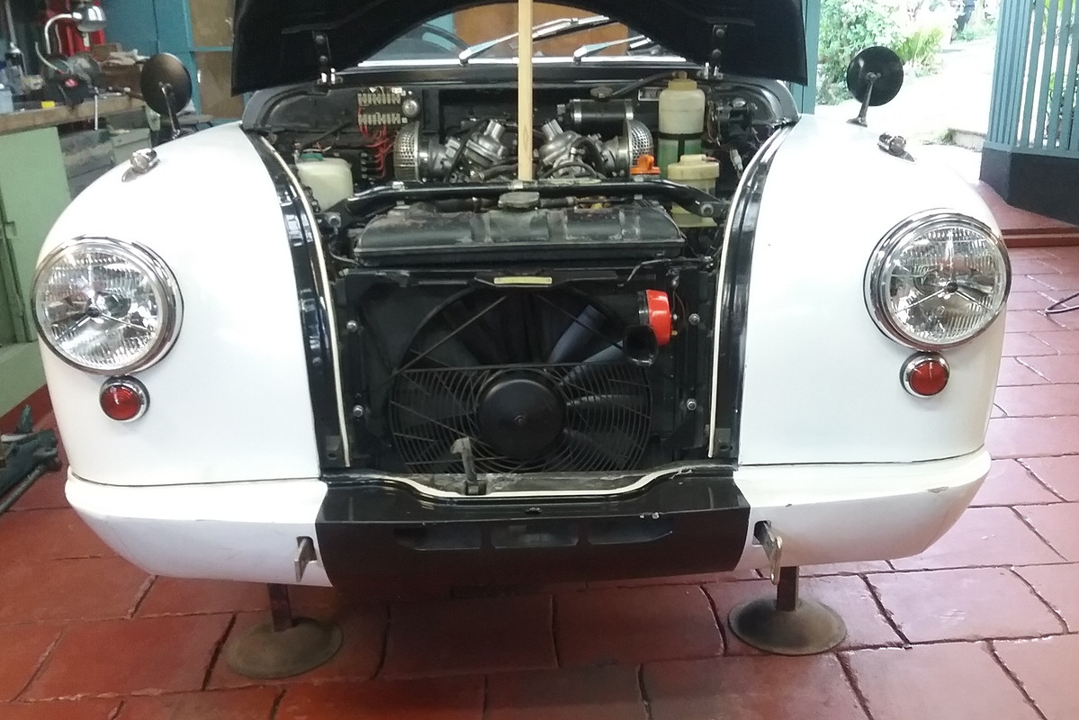 then the nudge bar was fabricated from the table legs...  and fitted between the mounts. Note a bit of luck/serendipity. The driving light mounts (an integrated tube with a through bolt) fitted perfectly within the tube ends of the table leg fittings which are now the Fog light perches.  A swivel adjuster (allowing 10°-15° movement) was fabricated on the DS bar support. The securing bolt (1/4" UNF) can be seen near the support brace opening of the valance in the image. 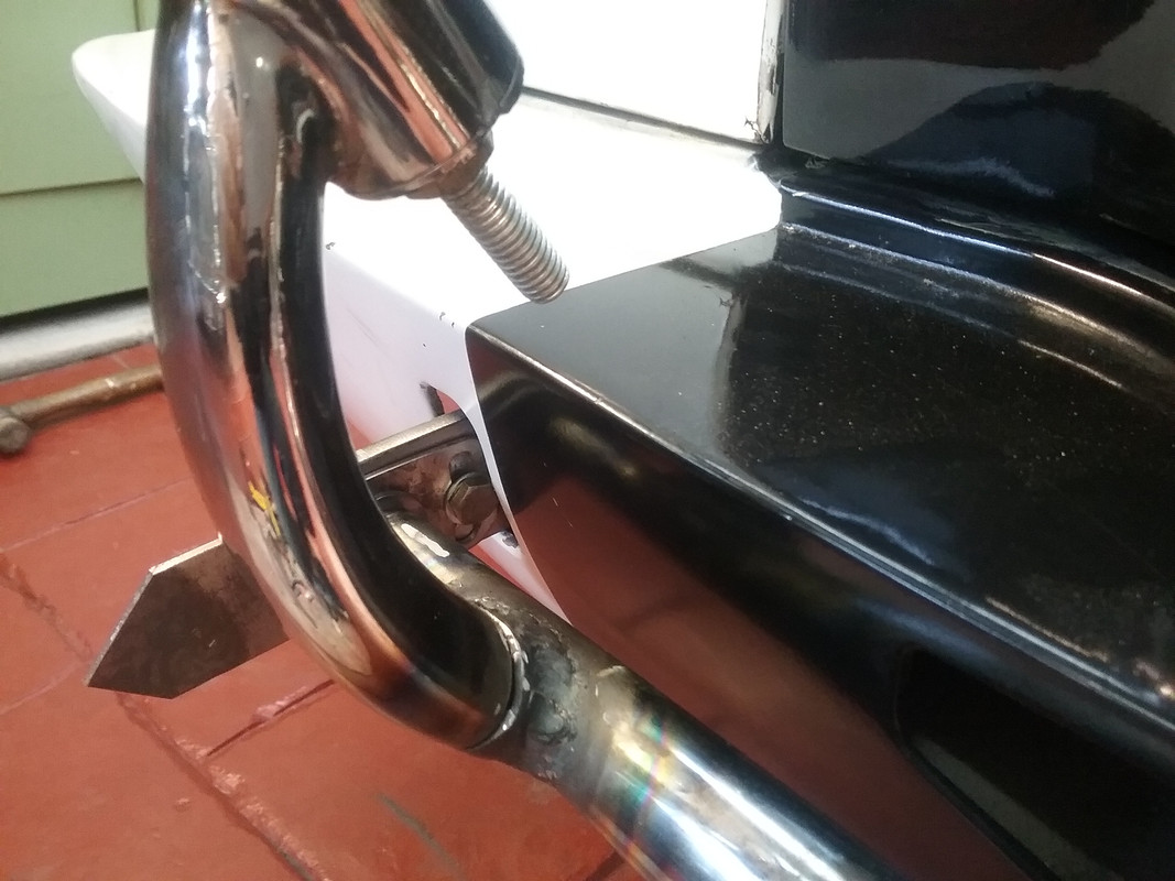 PS. There's still a bit of welding to do after which the welds will be linished smooth and the complete bar will be rechromed. Small bumperettes will be fabricated and cover both bumper supports and the tow loop on the PS. A number plate support will also be fabricated under the Nudge/Fog light Bar...finishing off the front of the car.
|
|
|
|
Post by johnwp5bcoupe on Aug 29, 2019 14:08:24 GMT
You don't waste a lot of materials Vince is the wife's ironing board safe  well done as usual  |
|
|
|
Post by enigmas on Aug 29, 2019 21:19:39 GMT
I like recycling stuff John. It's interesting what possibilities can be seen in apparently junked objects  My wife has an art background so she's really no different from me in these things. As for our grown girls...they're both minimalists, a lot of stuff will go straight into the skip when the time comes. PS. We don't iron anything!  |
|
|
|
Post by johnwp5bcoupe on Aug 30, 2019 7:19:38 GMT
I like recycling stuff John. It's interesting what possibilities can be seen in apparently junked objects My wife has an art background so she's really no different from me in these things. As for our grown girls...they're both minimalists, a lot of stuff will go straight into the skip when the time comes. PS. We don't iron anything! I am a bit like that Vince I keep bits of Ali Steel and Brass and say "that may be handy one day" and it's surprising how often I dip into my scrap bits |
|
|
|
Post by enigmas on Aug 30, 2019 9:12:39 GMT
I finished welding and linishing the Nudge/Fog Light Bar today and that virtually concludes the work to the front of the car excepting a number plate bracket. The bar and the the 2 front removeable mounts will be sent off for chrome plating.  |
|
|
|
Post by Warwick on Aug 31, 2019 7:44:12 GMT
I like recycling stuff .... Vince, I think you'll find that it's now called repurposing or reimagining. |
|
|
|
Post by enigmas on Jan 18, 2020 4:19:28 GMT
A Little Repair/Maintenance on the Coupe.Front Suspension Work. I've managed to put some time in between the heatwave and the air pollution currently hanging over Melbourne refurbishing the front suspension/bushes. Most of the work is straight forward but there's always something ready to bite back when you do these maintenance tasks. The rear lower front suspension arms pivot on a brace bolted to an internal plate inside the monocoque frame. Four UNF bolts hold this pivot brace in place. The brace takes all the front brake reaction loading; virtually the full weight of the car pushes against this brace when under brakes. So its a vital component that needs to be securely fastened. Unfortunately after removing the existing 4 bolts on the driver's side 2 were found to be loosening when retorqued. This was due to the threads on the internal plate being compromised or partially stripped...old age and internal corrosion perhaps? Fortunately I have a range of suitable bolts in a stash and decided to use 8 metric socket head high tensile bolts that were slightly larger in diameter to remedy this situation. I also have the appropriate metric tap so the fix was straight forward. A few pix below show the process and also some bits and pieces including 2 red nolathane bushes on the load side of the pivot. Once this side is sorted I'll move onto the passenger side and repeat the process. Here's a few pix of the task and parts used.  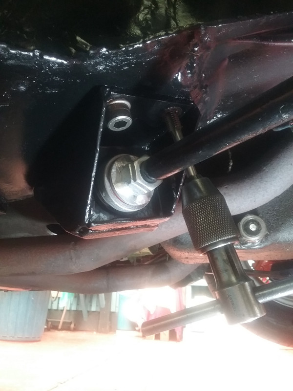 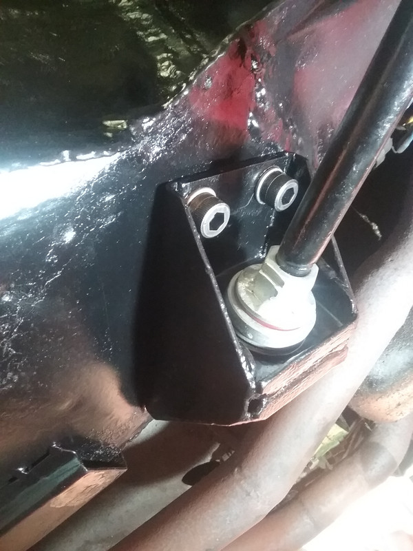 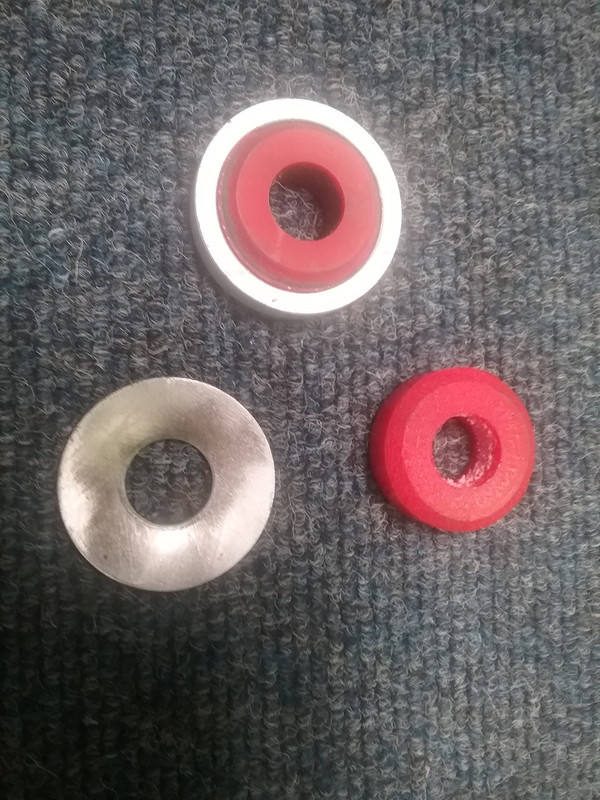 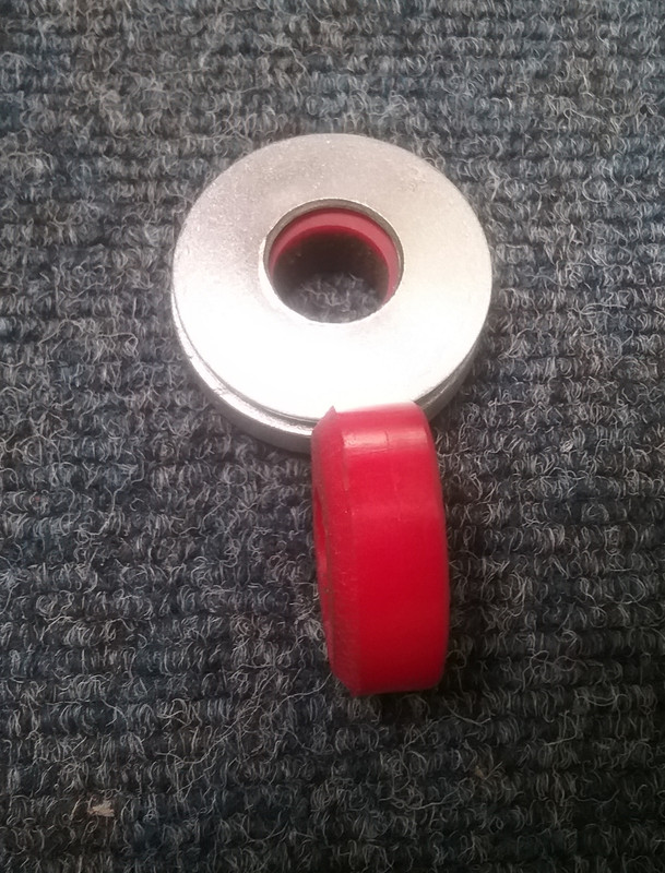 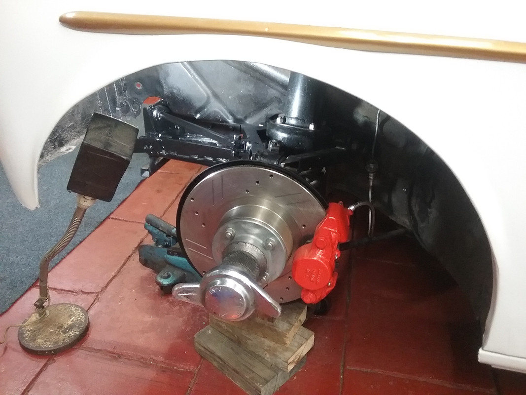 And a little follow-up below. (Several weeks later) Radiator Refurbish.After refurbishing the front suspension (brakes & bushes, etc) I also thought it timeworthy to send off the radiator for a clean and pressure test. Unfortunately being an original core (c. 1966) it needed a bit more than that, so ultimately I had it recored. The engine/trans lump is also scheduled to be pulled for an engine bay clean-up so it definitely seemed like the appropiate thing to do. * For anyone wondering about the radiator's origins...it's not a Magnette or BMC product but from a 1966 Valiant AP6. It was designed to cool the Valiant's 225ci slant 6 engine so works very well with the 215 ci (3.5 litre) SD1 V8 fitted to my ZB. Here's a few pix. 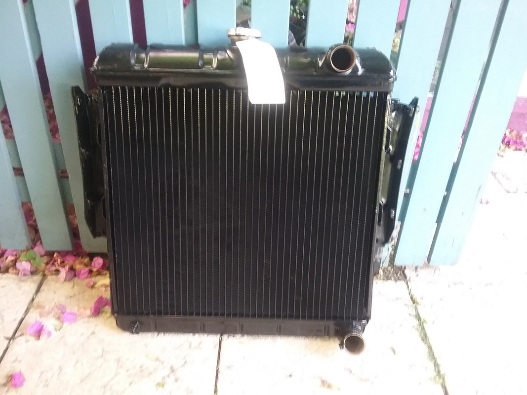 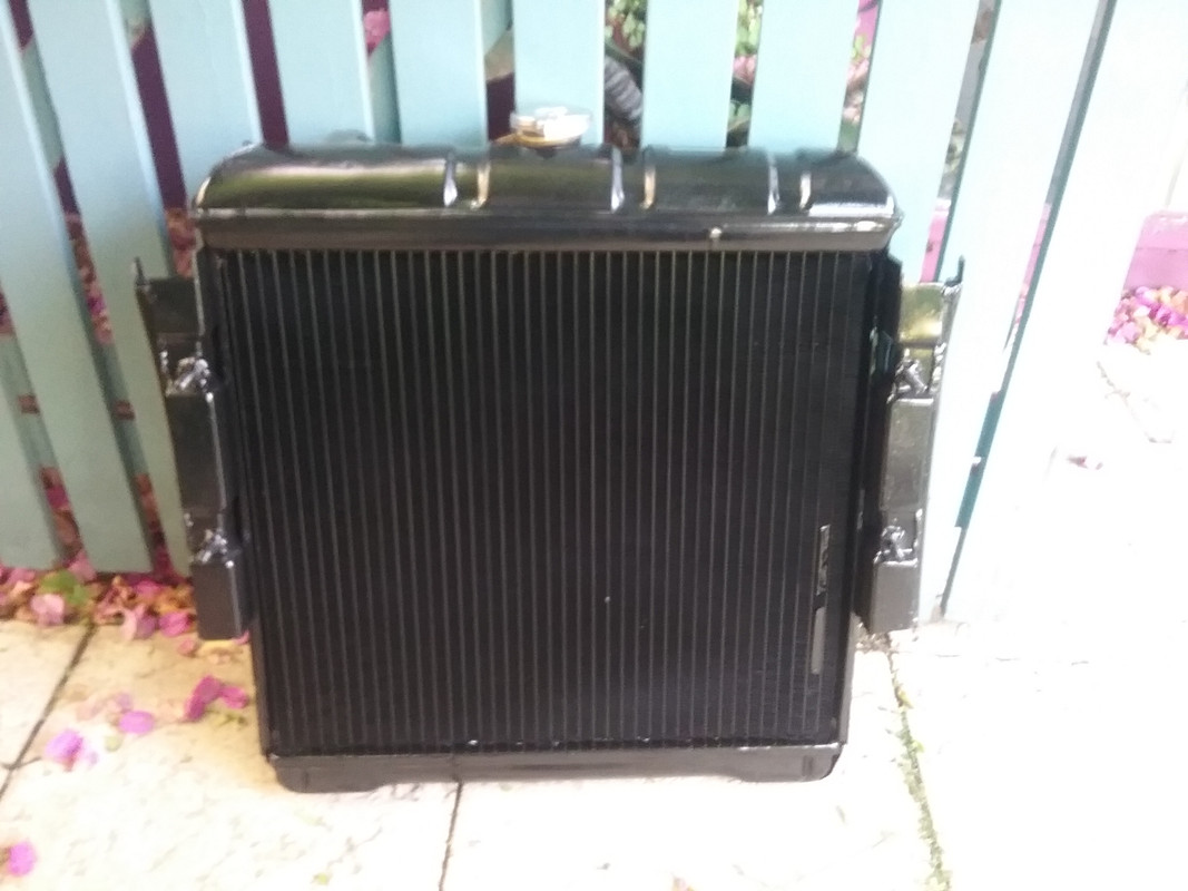 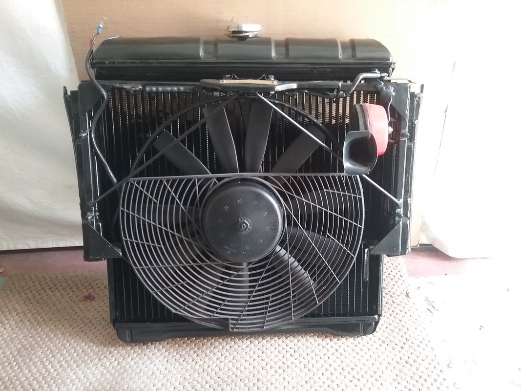 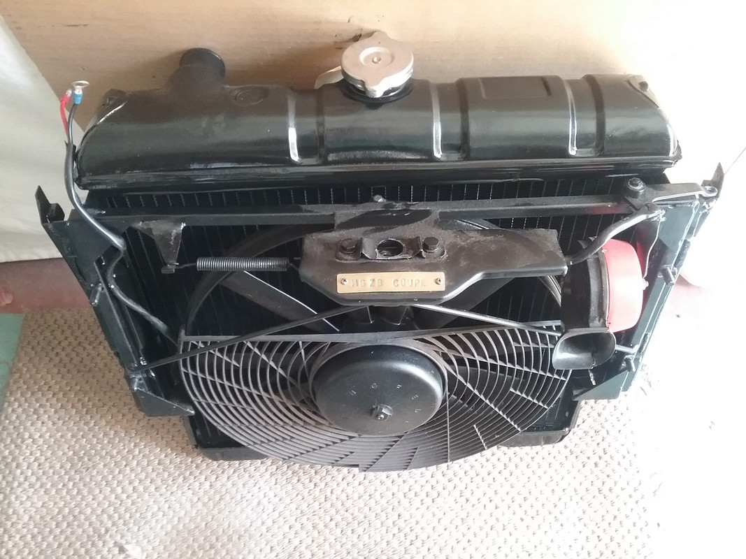
|
|
|
|
Post by enigmas on Jan 27, 2020 9:51:25 GMT
Home made 'Toe-In' alignment tool.Since refurbishing the front suspension (bushes, paint, general clean-up) including aspects of the steering rack as it's been physically moved slightly forward, I thought it would be an opportune time to check the toe-in alignment of the front wheels. The WSM specifies that the wheels be parallel with nil toe-in or toe-out. So the measurements are quite straight forward. To get the alignment correct I knocked up a home made tool using some 1" square thin walled steel tubing from the remnants of a bed frame that had been left out as hard rubbish by a neighbour. Below are some pix of the tool/device. 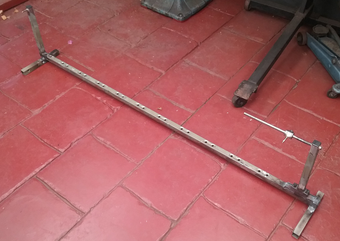  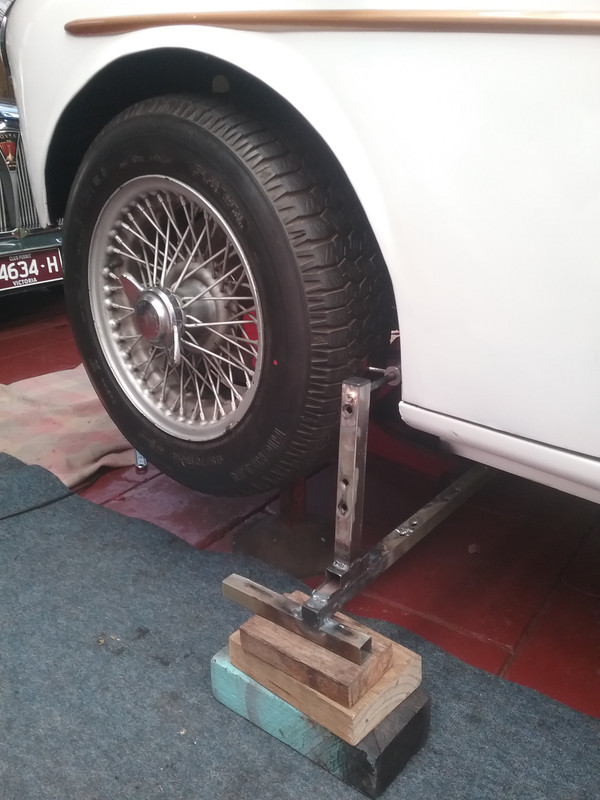 1. To use the device simply mark each tyre with a paint pen. 2. Position the pointers to match the marks. 3. Then rotate the wheels 180° 4. Move the tool to the front & check the alignment with the pointers. 5. Adjust for half the difference in measurement if required. 6. Rotate the wheels 180° to the rear again. 7. Move the tool to the rear and check the alignment. 8. It should now be correct. If not...repeat process 2 - 7. NB. The red dot on the outside face of the tyre is to quickly locate the locations of the 'alignment' points on the tyres. * If the car requires a toe-in alignment do the following. 1. Get the steering centred first, 2. then get the wheels parallel as explained above. 3. Then add up the total toe-in required (for example 1/16" + 1/16" = 1/8") 4. Subract the 1/8" from the total parallel number. 5. Move the device to the front and use the pointers to the indicate this new measurement. 6. Screw-in each tie rod arm 'equally' to reflect the required toe-in. So much for requiring expensive equipment to do these basically simple adjustments! Note. In the end the wheel alignment is only as good as the overall condition of the car's steering and front suspension systems, regardless of the high tech equipment that may be used to adjust it.
|
|
|
|
Post by enigmas on Feb 28, 2020 11:37:54 GMT
|
|
|
|
Post by johnwp5bcoupe on Feb 28, 2020 15:05:26 GMT
Super job as usual Vince you cant stop a good shed engineer Just took my sons C30 Volvo engine out I wont be doing another one after his new lump goes in !!!! |
|
tonys
Rover Fanatic

Posts: 419
|
Post by tonys on Feb 28, 2020 19:16:40 GMT
Excellent work and updates, the photos really show the work much better than just a written description. The MG air filter is a nice finishing touch |
|
|
|
Post by enigmas on Mar 9, 2020 6:51:03 GMT
Here's the next update on my ZB Magnette Coupe. It may also prove of value to any P5B owners as part of the update incorporates checking and replacing the timing gear set on the Rover V8 (actually an early SD1 version) and also a little mod to direct some engine oil onto the timing gear set from the engine valley. Engine/Trans & Bay TidySince pulling the motor & trans combo out of the ZB a couple of weeks ago I've been preparing things to both paint and tidy the engine compartment, as well as do some light maintenance on the engine, trans & ancilliaries. I've ordered a VRS set, will replace the front and rear main seals (if needed) and have pulled the timing cover off to check the timing chain set; this will also be changed. As always seems to happen when engine components are removed, especially when bolts enter water galleries, issues occur. In this instance a long bolt was seized and sheared off as it was removed at the block face. This always adds some fun & games when attempting to extract the objectionable remainder. The images below illustrate the method I used to remove the harmonic balancer and extract the sheared stud. To conclude, I've added a little video below to illustrate the wear on the timing chain...which is quite considerable. 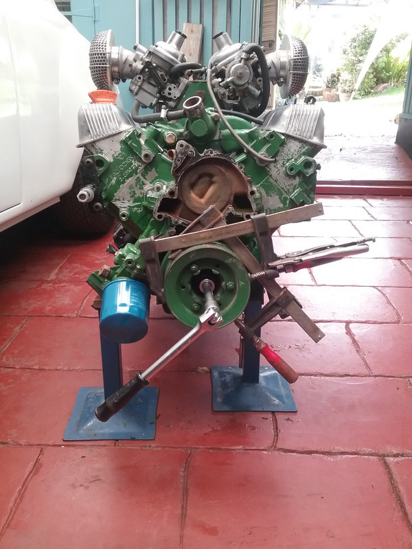 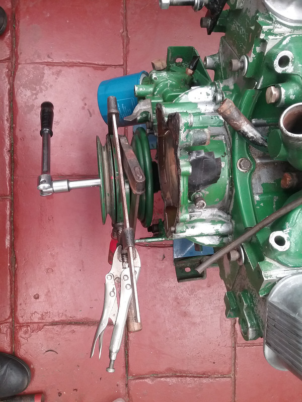 Sheared bolt 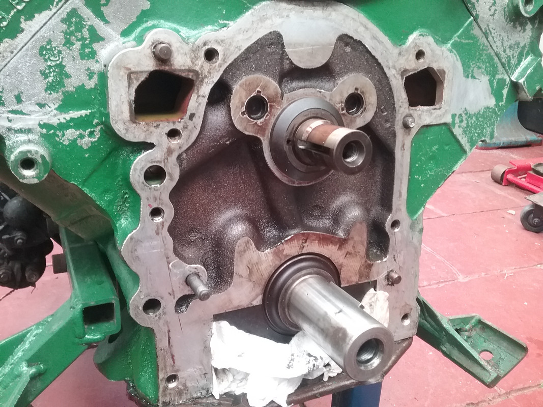 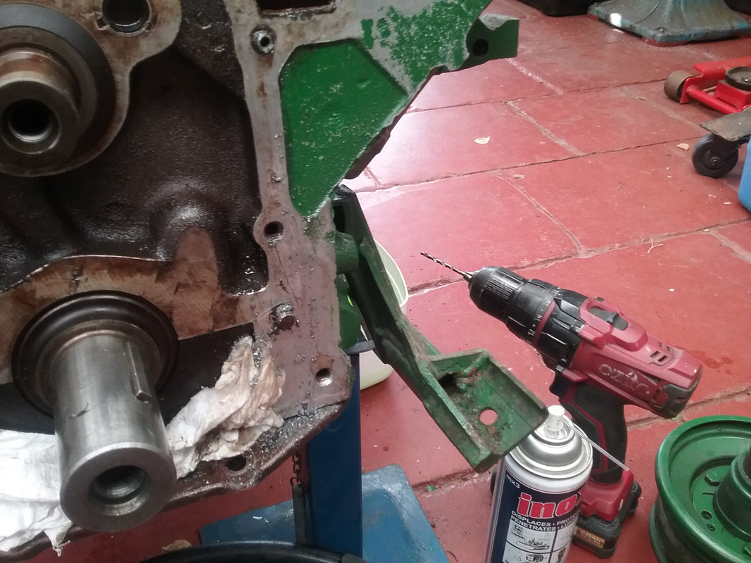 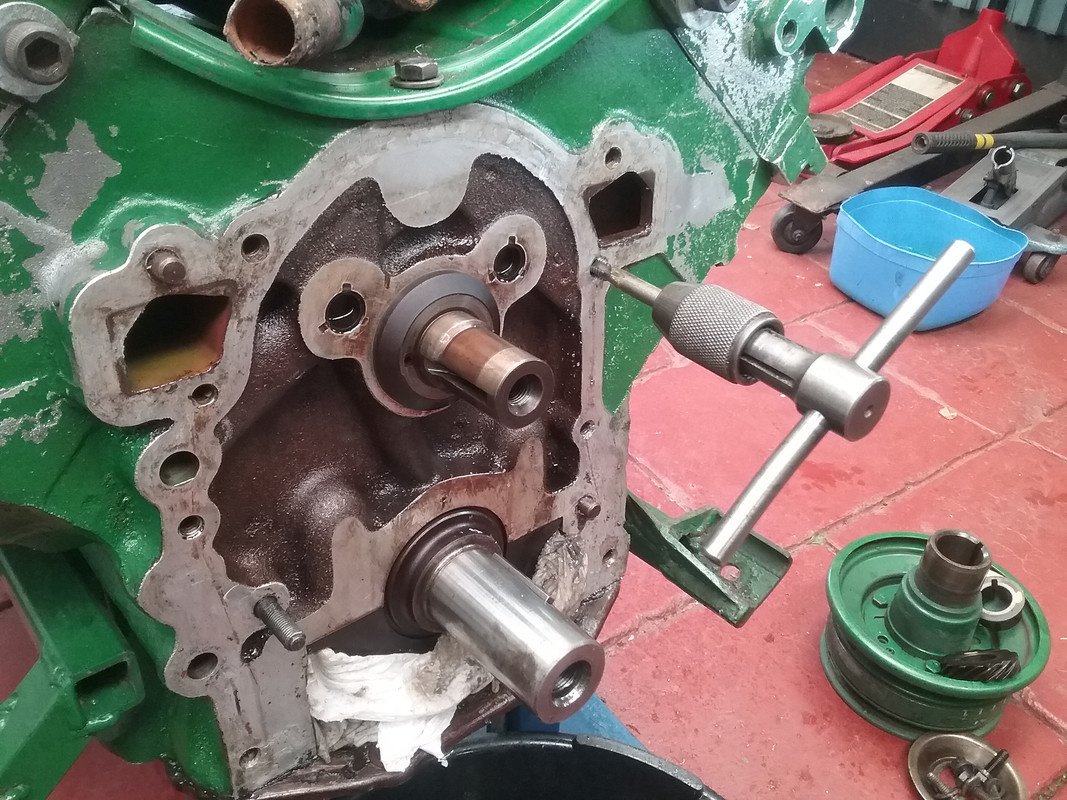 This is another small mod to direct oil from the valley to the timing chain set. Note the 2 3/8" (10mm drilled holes) 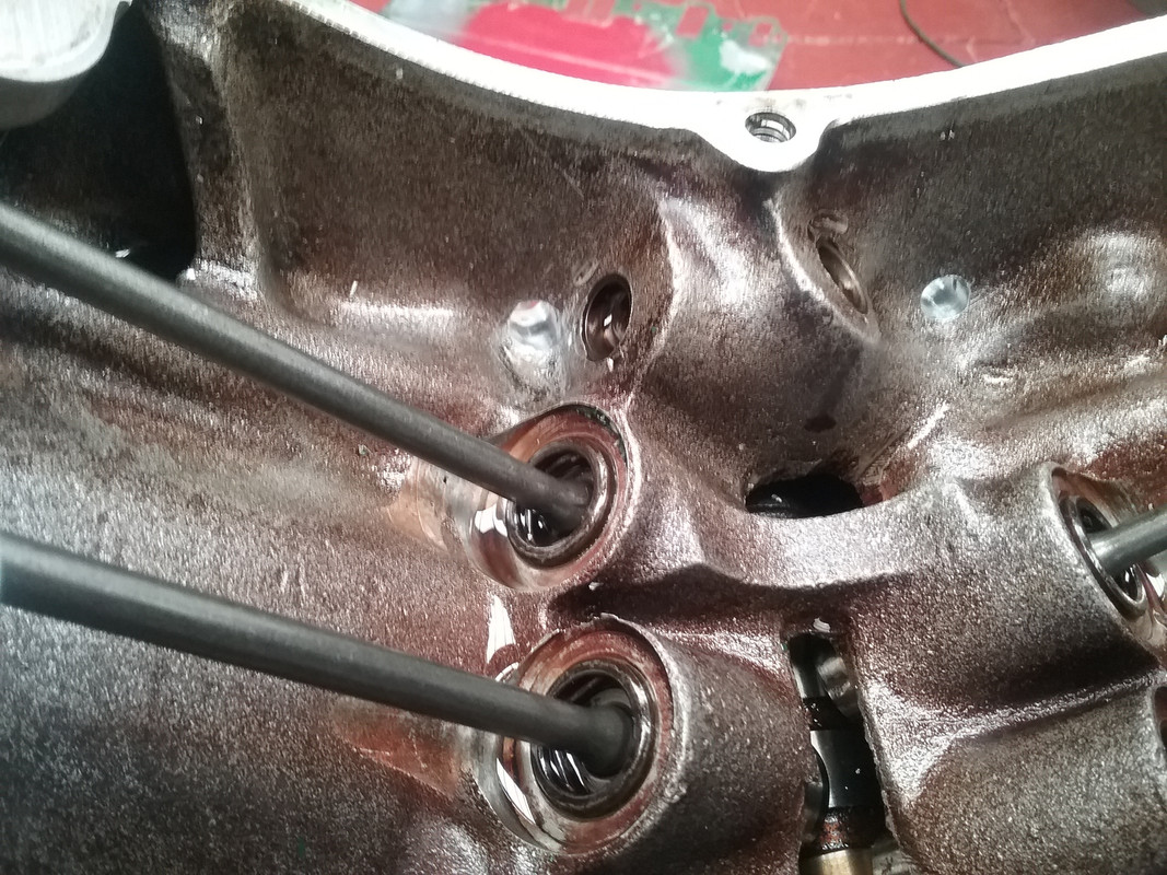 This is where they exit. 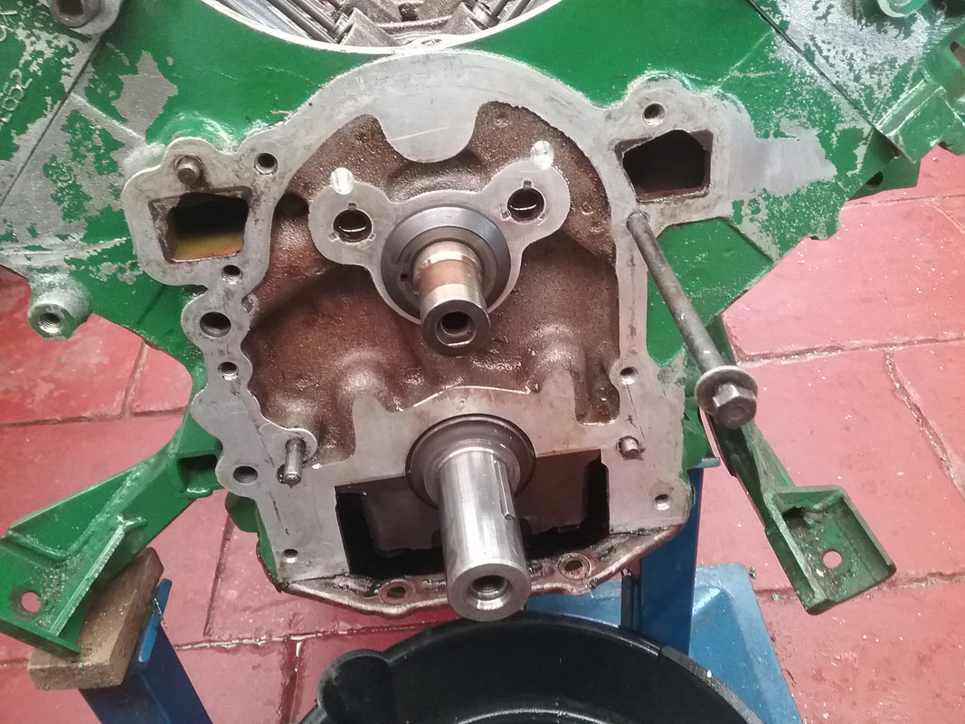 These are the new timing gears (mi us the chain for the moment) sitting in place  Here a short video illustrating the slack on the worn timing chain set. |
|
|
|
Post by johnwp5bcoupe on Mar 9, 2020 8:54:12 GMT
Nice one Vince good info |
|
|
|
Post by enigmas on Mar 10, 2020 9:37:31 GMT
Working on the Bling.I managed to prep and paint a few items today. The colour is MG Burgundy it's an automotive engine enamel that's both heat and chemical resistant. The appearance is a deep burgundy unless seen in direct sunlight. Here's a few examples. A bit of primer first. 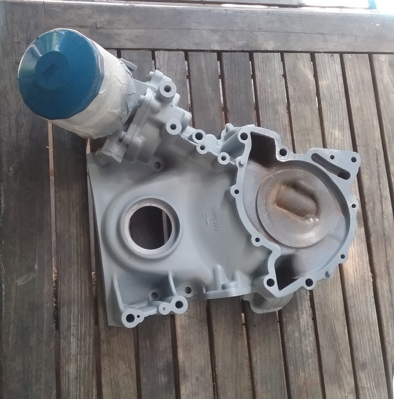 I painted the pieces using a small touch-up gun. 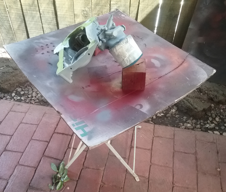 Here are the items in various light sources. 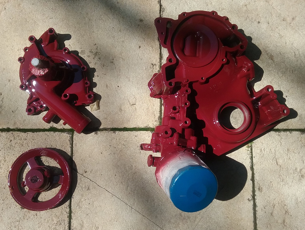 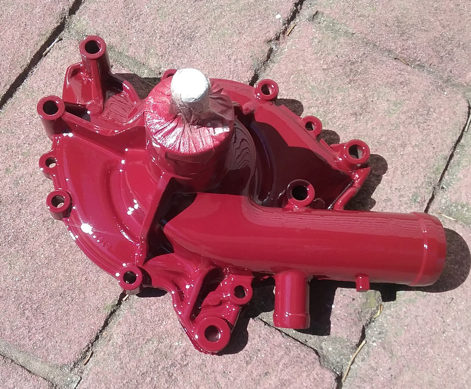 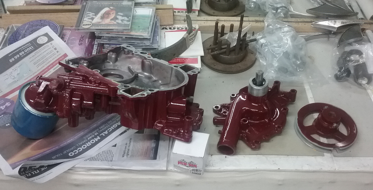 and last but not least...the water pump and pulley assembled. 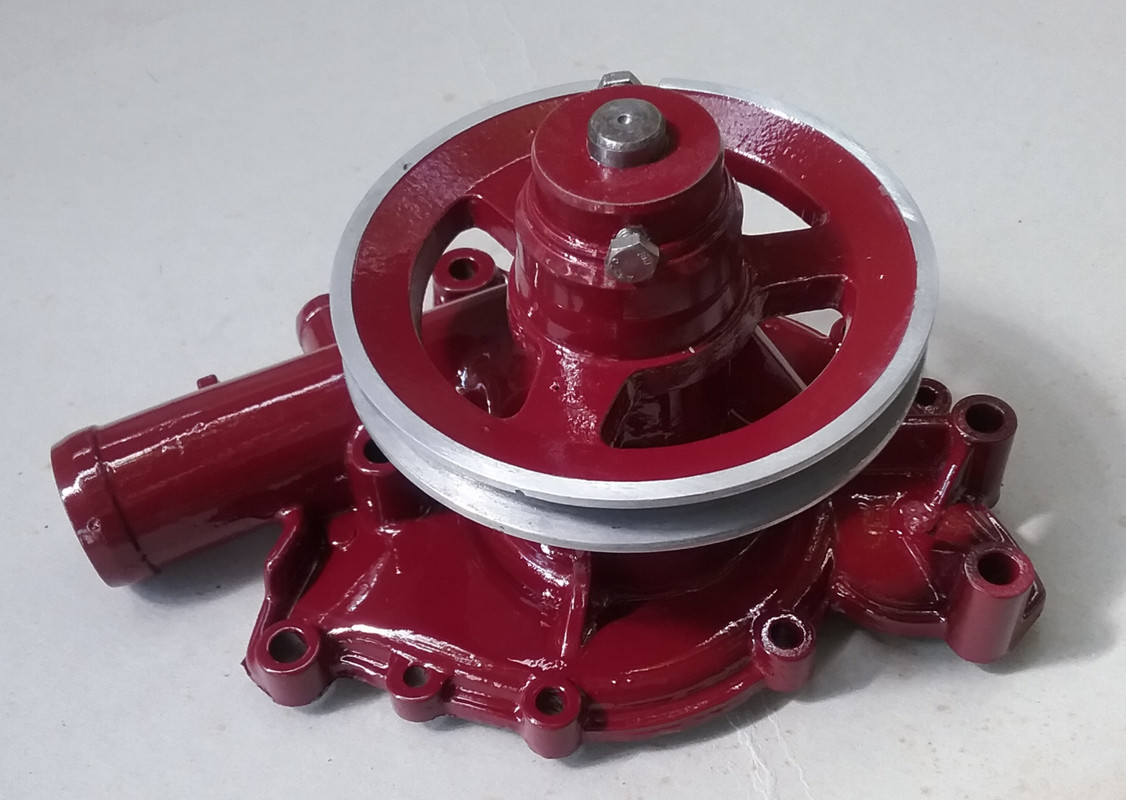
|
|
joffa
Rover Rookie

Posts: 82 
|
Post by joffa on Mar 14, 2020 23:07:20 GMT
Brilliant build and superb attention to detail. Quick question - that adapter plate mating the 3.5 to the Triumph gearbox, was that ever commercially available from anywhere or East or is it a full custom job at home? Been tossing up options for a while and due to a number of spare Triumph overdrive boxes in the garage it has always been an option I would like to explore. Not the strongest box in the world but if the layshaft mod is done (needle rollers go and machined bush goes in) they hold up a bit better and you get the overdrive on 3rd and 4th which is great. Great thread and can't wait to see it finished.
|
|
|
|
Post by enigmas on Mar 15, 2020 3:54:16 GMT
Hi Joffa...the bellhousing adaptor & other related components are things I designed to adapt the SD1 Rover V8. I've had several engine trans combos in this Magnette including a complete Triumph 2.5 PI engine. When I decided upon the V8 I wanted to retain all the transnmission from the engine back. The final drive unit is a narrowed V6 Ford Capri unit with a 3.0:1 ratio so suits the V8. The pieces are not something you can buy over the counter. The bell-housing adaptor is a combination of steel plate and strap steel, flame cut where required for the flanges and the strap rolled into a circle then welded between the flanges to form the adaptor. I'll be removing the gearbox to clean/regrease/lube the clutch cross shafts & related assemblies as part of this freshen-up, so you'll see these pieces. The assembly within the custom bellhousing adaptor comprises a V8 automatic driveplate for the starter and a billet steel flywheel that takes the Triumph diaphram pressure plate. The brand 'new' pressure plate was 35 grams out of balance when first fitted causing a monumental vibration above 2000 rpm. It took me quite some time to identify the problem. As the engine minus the pressure plate was completely rebalanced when I rebuilt it, the logical conclusion was that the imbalance issue could only be the add-on component...which was the pressure plate. Typically the assumption is that a new component would be balanced during manufacture. Best not to assume! Here are a few old pix of the instalation. Engine and driveplate with steel flywheel combo. The trans adaptor is not shown here. 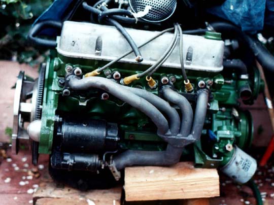 Brand new but 'out of balance' (by 35 grams) pressure plate. 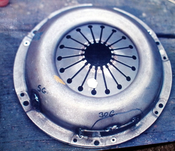 |
|
|
|
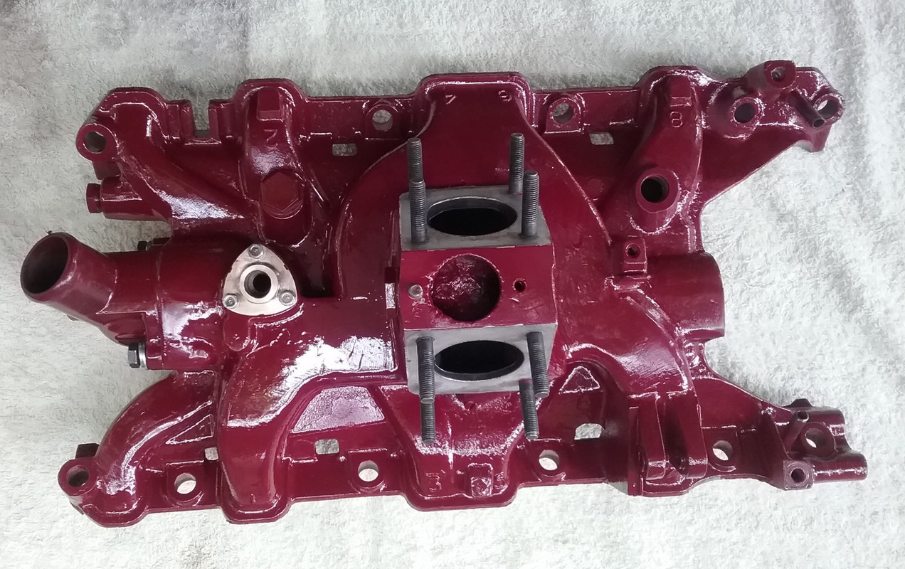
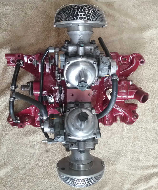
Post by enigmas on Mar 20, 2020 13:30:25 GMT
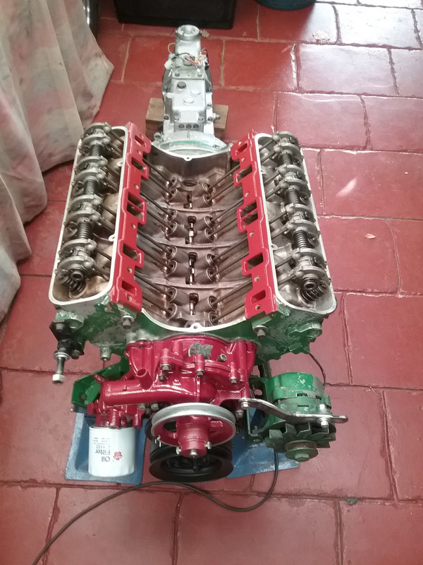
SD1 Rover V8 Engine_Inlet Manifold ModsI've started fitting/bolting-up a few components back to the engine and have also decided to lightly modify & massage the inlet manifold in the process. The rear coolant outlets on the cyl head of the alloy Rover V8s alway seem to suffer a degree of corrosion as the ports are effectively blocked off by the inlet manifold design at the rear. The PS coolant port showed evidence of corrosion as well as providing a repository for sludge and coolant debris. Interestingly the DS port illustrated neither. I can only surmise that coolant flow in the block creates this unusual situation. This engine runs twin Zenith Stromberg CD carburettors fitted with coolant controlled autochokes (not like the AED of certain SU carburettors). As such they require heated coolant to flow through 2 capsules fitted to the sides of the carburettors. These capsules heat a bi-metallic coil which in turn affects the delivery of additional fuel during the warm up period. To this end and because I didn't like the current provision for directing coolant to these capsules I decided to provide coolant ports from each of the rear cyl head coolant passages. I also had to repair surface erosion on the manifold flange face on the PS. This was done by using a special 2 part filler designed for alloy refrigeration system repairs. Here are a few pix of the tasks currently under way. 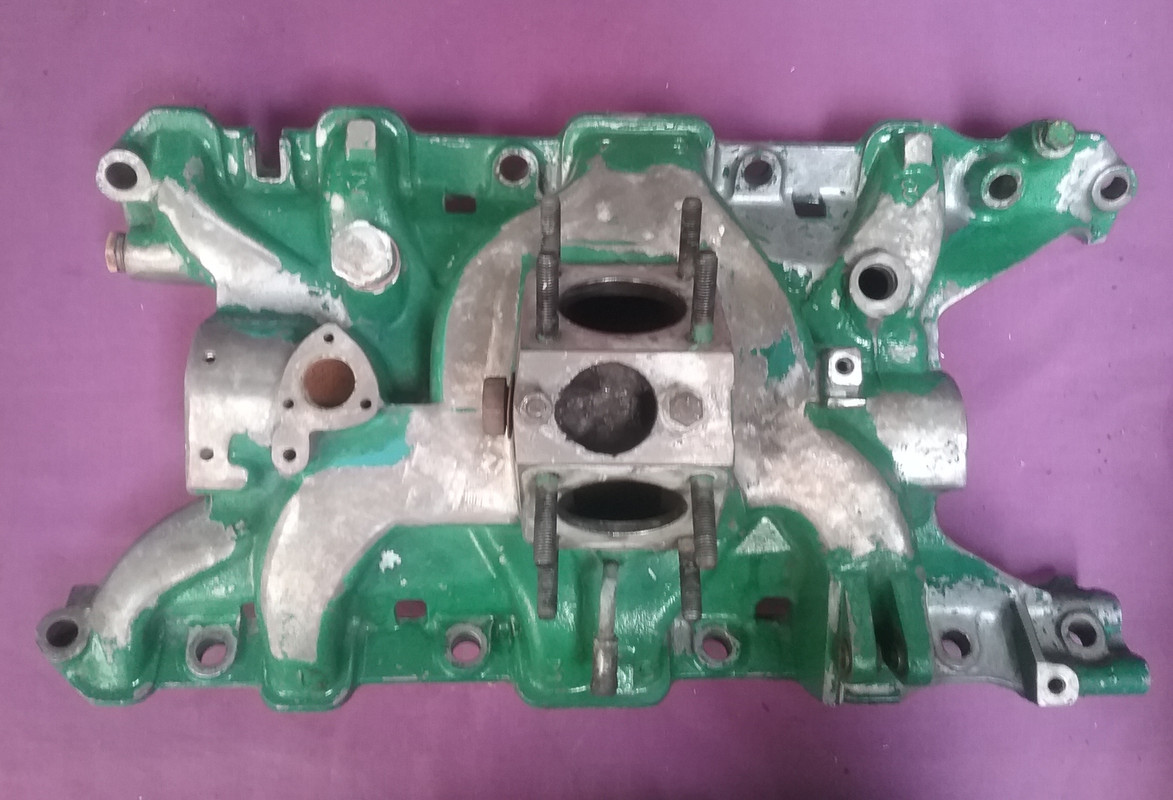 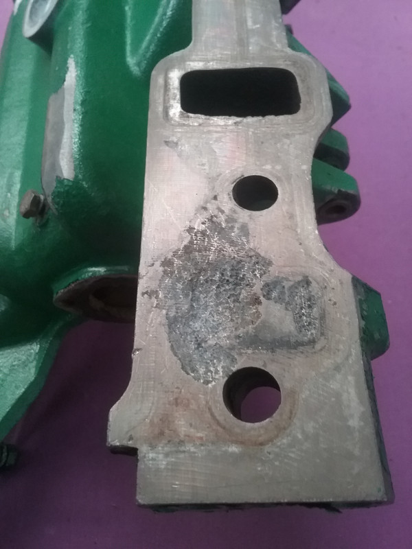 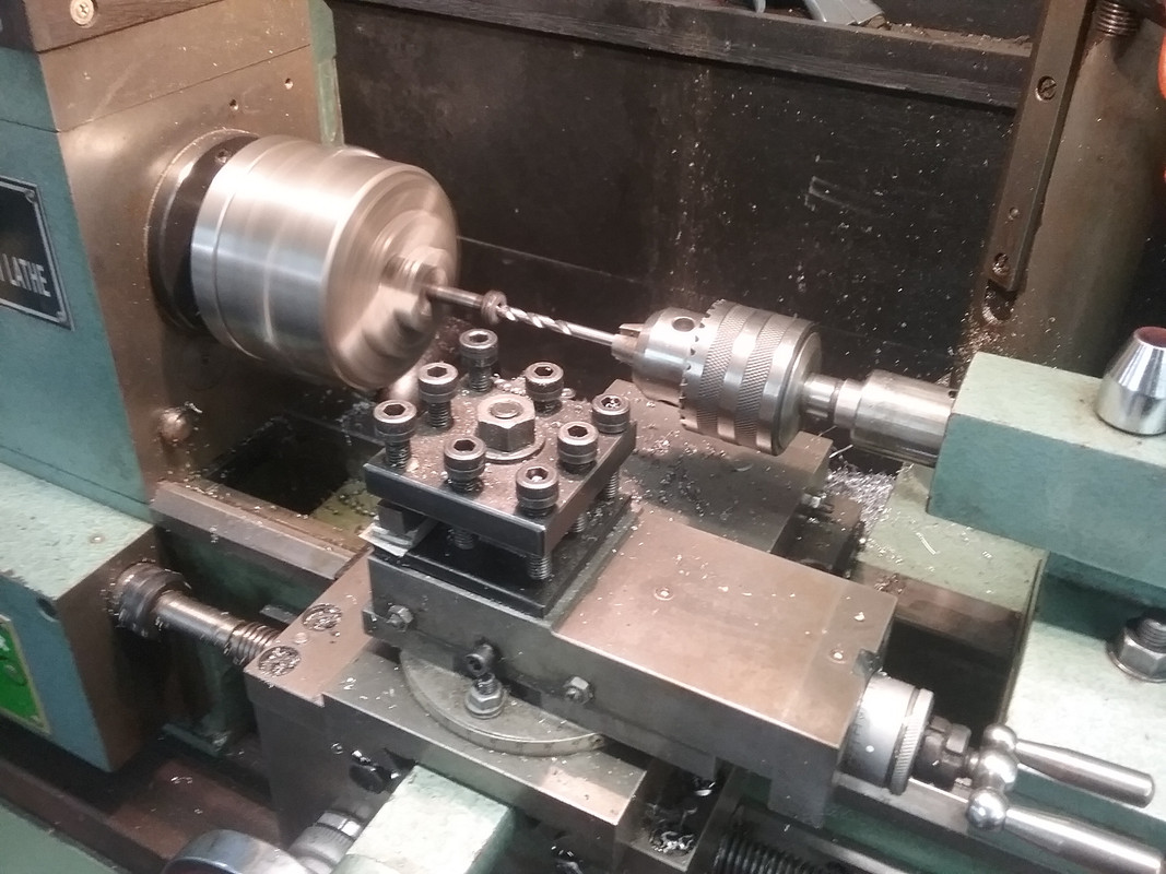 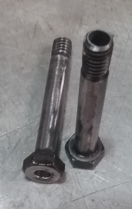 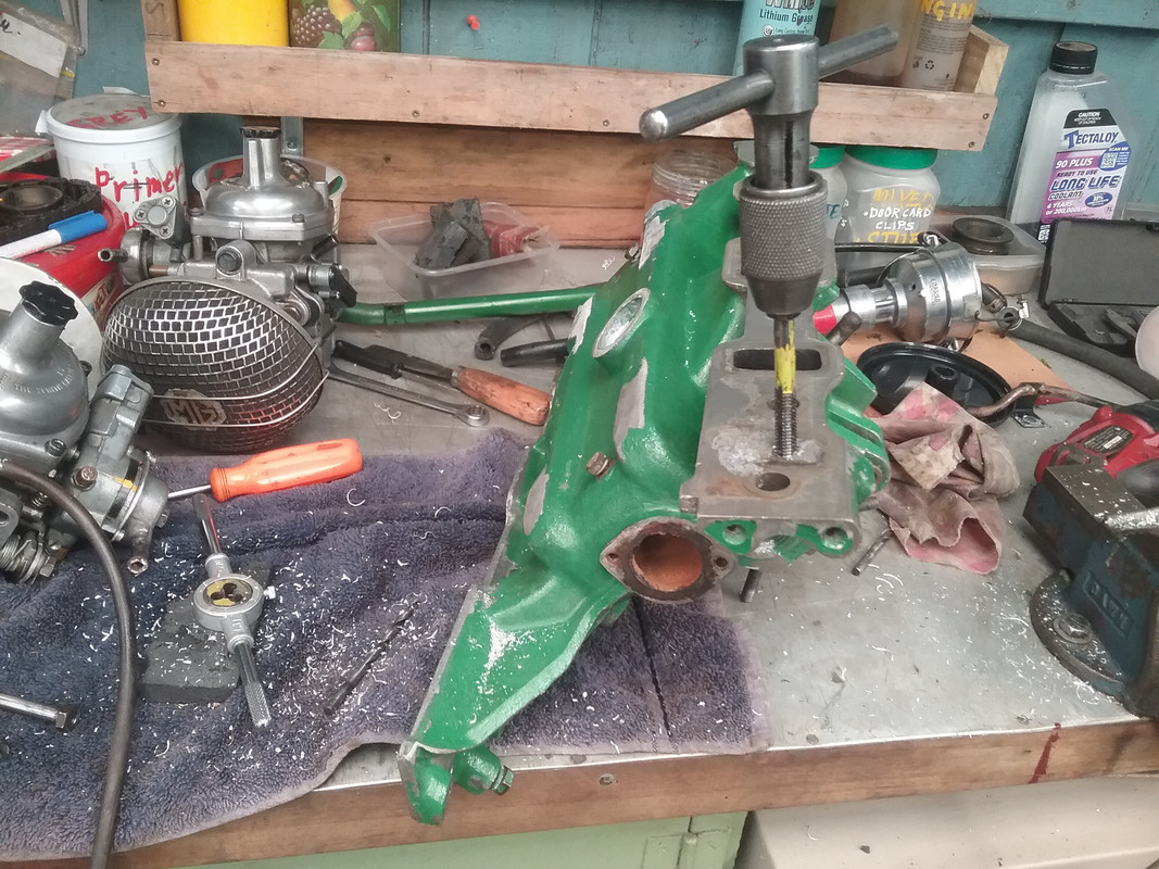 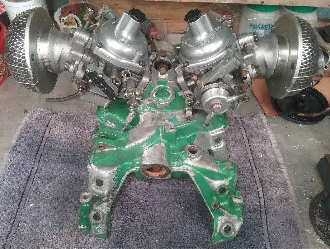 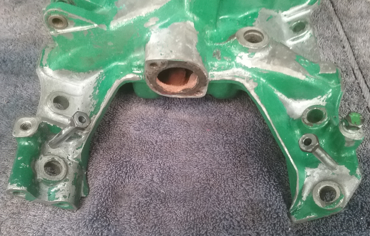 ...and this is the engine with a few of the components back in place prior to removal of the inlet manifold for repairs/modifications. A new timing chain set, front main seal and freshly cleaned and painted sump have also been fitted todate. Note: The rocker covers as currently seen are not the ones that will be fitted. All the green areas seen will be painted MG Engine Red (actually a burgundy) as seen on the front covers. 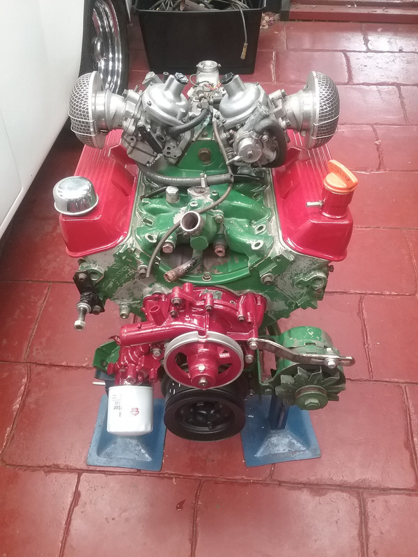
|
|
|
|
Post by djm16 on Mar 21, 2020 1:56:54 GMT
How did you balance the pressure plate?
|
|
|
|
Post by enigmas on Mar 21, 2020 11:08:18 GMT
When I was rebuilding the engine and also adapting the Triumph overdrive gearbox I needed to ensure the custom pieces that I had fabricated were all in perfect balance as they are directly bolted the the rear crankshaft flange. The engineering company I entrusted this work to also had a balancing machine, so all the individual pieces were added to the crankshaft assembly spun up and checked.
Once fully assembled the only component that wasn't checked for balance on the assembly was the pressure plate as it was brand new and a Factory piece. So then it was merely a process of deduction. Fortunately the engineering company had another Rover crankshaft at hand and used that with my other add on components to check the balance of the pressure plate.
The moral to the story is...just because a component is new or reconditioned don't assume that it's fit for service. Similarly, I fitted a recon torque convertor from a reputable company to my P5 coupe years ago only to discover that it created a harmonic at exactly 60 kph. Only years later did I learn the reason for this harmonic which was explained to me by a rival company.
|
|
|
|
Post by djm16 on Mar 22, 2020 5:49:01 GMT
Thanks for that. I was hoping you had some nifty way! I was in the identical position. My P4 engine had a dreadful vibration that was easily narrowed down to the pressure plate. Fixing it though required an engine strip down and re-balancing the crank and every attachment. It is probably worth knocking up something on you lathe to balance a pressure plate separately. When you have it, would you let me know. |
|
|
|
Post by enigmas on Mar 22, 2020 6:38:10 GMT
Sure David. All the add on components (excluding the crankshaft, conrods, pistons including the rings and harmonic balancer) were balanced individually. So I just need to check any fresh component that I add. As an aside, I can't see that I'd be wearing out any of these engines (in my classics) at this point in my life. If I do decide on an engine rebore (which I won't) all that is required is to match the new piston weights with the old set. Anyway...I tend to prefer racing clearances...motors run better when they're loose. * Just in case you're concerned about oil pressure...consider the 10 psi rule (Smokey Yunick). For every 1000rpm on a street engine all you require is 10 psi. All the Rover V8s (really a GM design V8) follow this formula and are extremely long lived. |
|
|
|
Post by enigmas on Mar 26, 2020 12:11:43 GMT
|
|
|
|
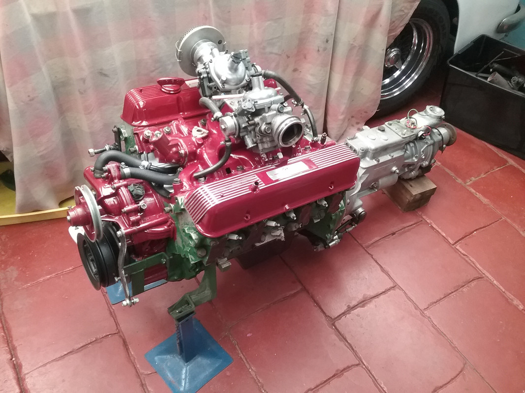
Post by enigmas on Mar 30, 2020 3:19:52 GMT
Over the past few days (thanks to the Convid-19 home isolation we're all currently going through) I've managed to finish most of the detail work on the engine and its ancilliaries (alternator, starter & distributor.) The new brass welsh plugs have been fitted and the ribbed/finned rocker covers carefully taped then sanded where I wanted the alloy contrasting against the painted surface. As the engine wasn't fully stripped I've been using an airbrush to finish painting the various engine surfaces as the spray pattern is easier to control. Next time (if I choose to do this again on something else) I'll place the engine further away from the car! With that done, I now need to remove the gearbox and lubricate the clutch release components and add a smear of high temp grease to the spigot bush. 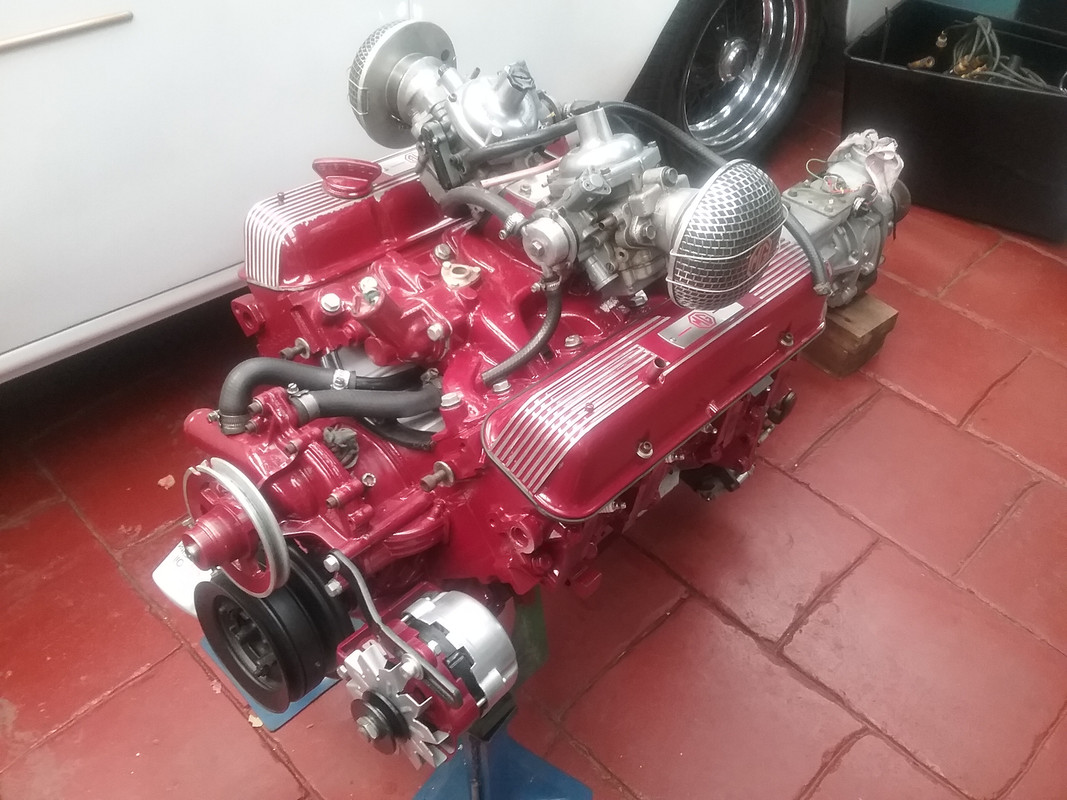 |
|
|
|
Post by enigmas on Mar 30, 2020 5:08:46 GMT
Just to add to the above I also primed the engine oil pump & galleries using an old distributor that I'd cut down and removed the drive gear that meshes with the camshaft. 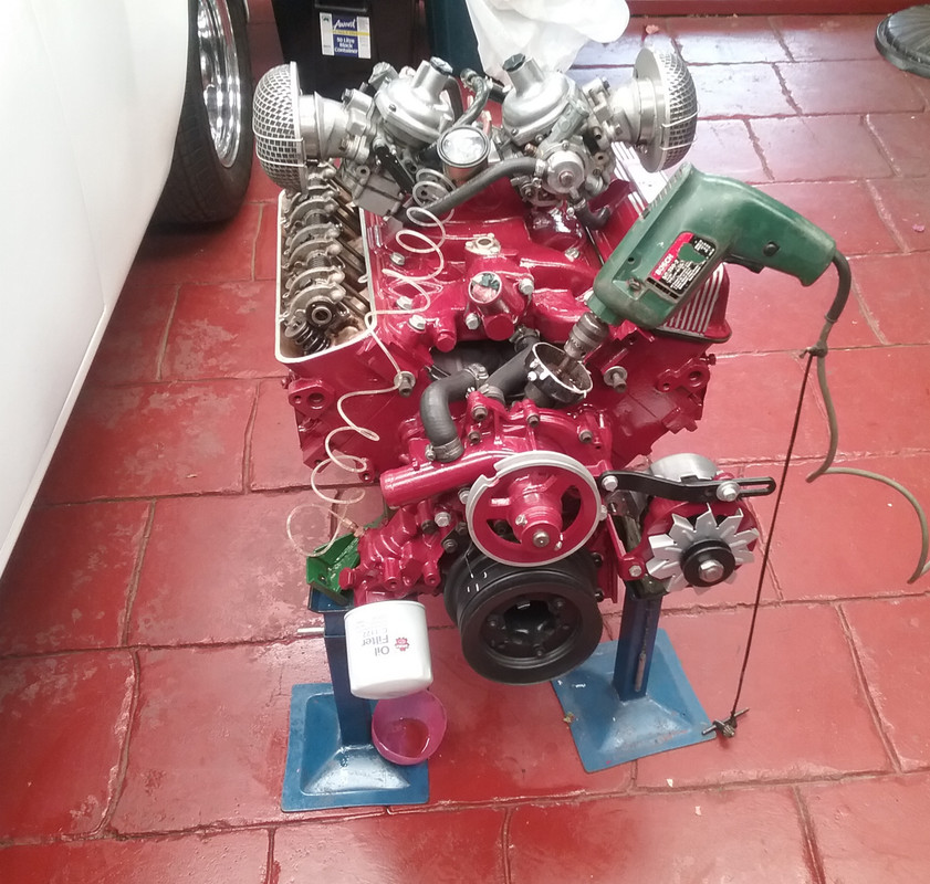 |
|


 well done as usual
 My wife has an art background so she's really no different from me in these things.