|
|
Post by enigmas on Aug 30, 2016 7:08:43 GMT
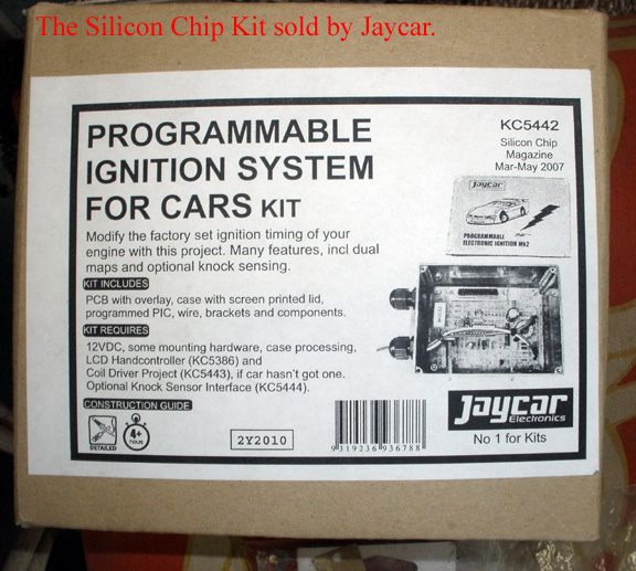
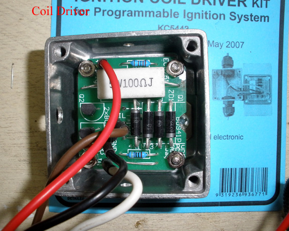
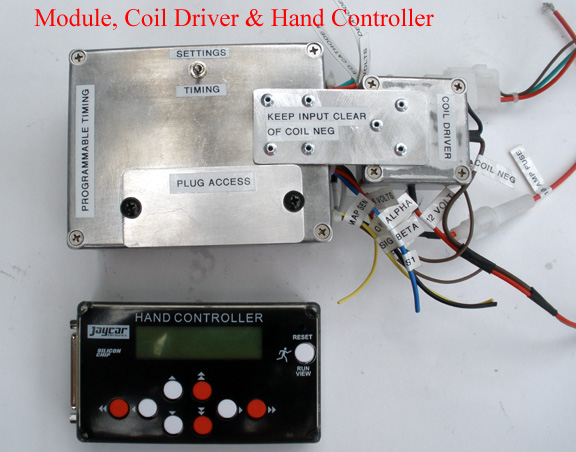
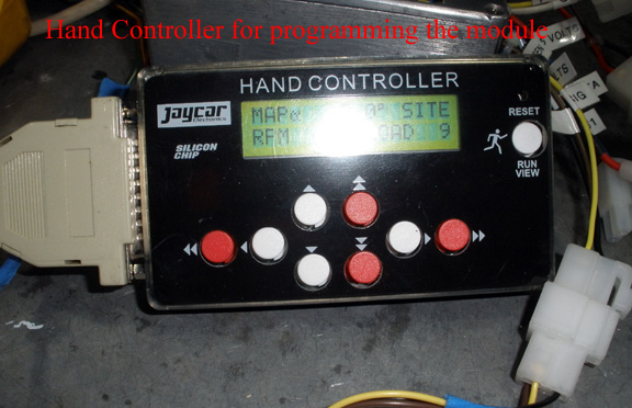
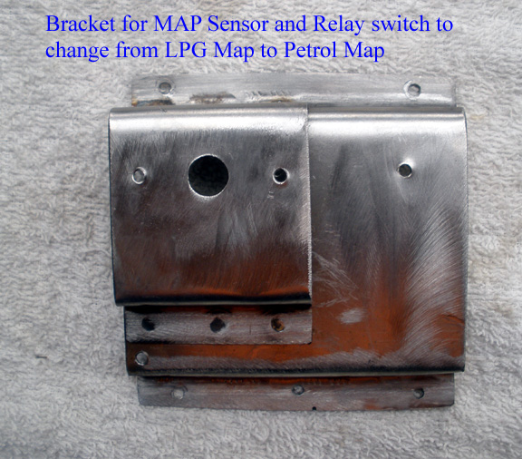
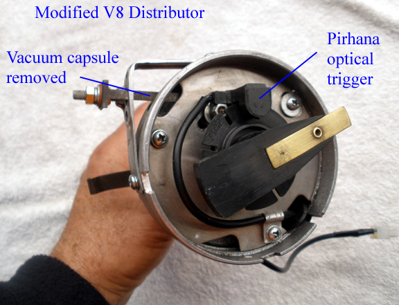
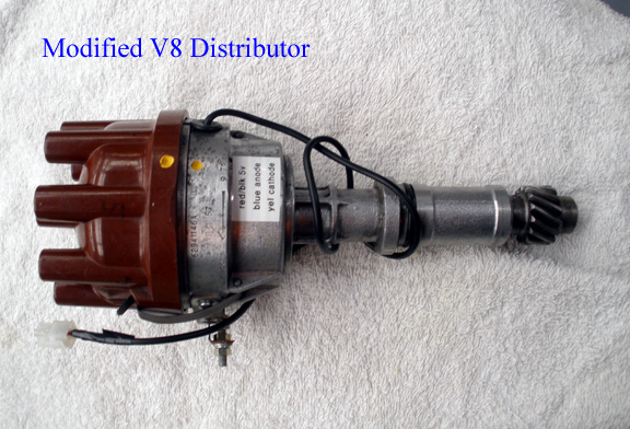
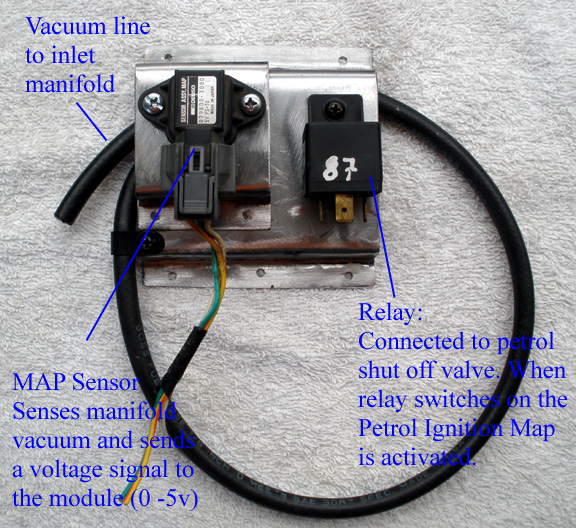
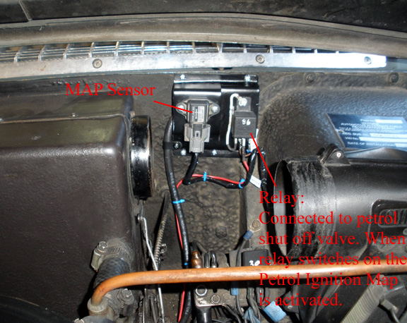
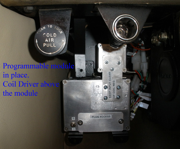
Preamble. Over the past couple of months I've been both doing some research and also assembling a Programmable Ignition Module for my Rover P5 Coupe. The module was designed by John Clarke of Silicon Chip magazine c.2007, (but please don't quote me on the date.) I decided to fit the module due to a recent trip that took me to Wangaratta about 100 kms from the NSW border. A trip taking about 3 1/2 hrs at legal speeds in convoy with the BMC/Leyland Car Club. Having reached Wangaratta I thought I'd refill the car's LPG tank. I pulled into a large, newly completed highway petrol station only to find, that of their 6 LPG pumps, only one was functioning. As my car is full time LPG this was somewhat disconcerting. The car did have 2 LPG tanks fitted at one stage but the second tank was removed several years ago to free some boot space. The rationale is to fit a small secondary fuel tank, perhaps 20 litres or less as a backup reserve fuel. As each fuel has differing ignition requirements, I wanted a device that would allow me to dial in a precise ignition curve for both fuels and for the engine specs. The motor (P76 V8) was rebuilt over 20 years ago and utilizes low compression Rover 3.5 pistons (8.13:1) yielding a compression ratio of 11:1 or cranking pressure of 215psi. This is a lot even then but sustainable on LPG. The programmable module would also allow me to design the advance curve to avoid pinging/detonation. A Manifold Absolute Pressure sensor (MAP) is used in conjunction with the programmed ignition map (or lookup table) to set the parameters. All of this of course leads to an engine that is smoother, more responsive and efficient with fuel. It's definitely not about hot-rodding. I fitted a Piranha Optical Ignition system to my car 20+ years ago and have a couple of these unit set aside. I also purchased a Silicone Chip Programmable Module kit a number of years ago and put it aside. It's essentially bag of electronic components that need to be assembled. The module can be programmed for either one 15 stage map or two 11 stage maps. One for LPG and the other for Petrol, available at the flick of a switch. It doesn't modify the original timing like most LPG processors do, but draws on 2 distinct ignition maps, each with different load and advance settings. There's even a knock sensor available which automatically retards the timing. 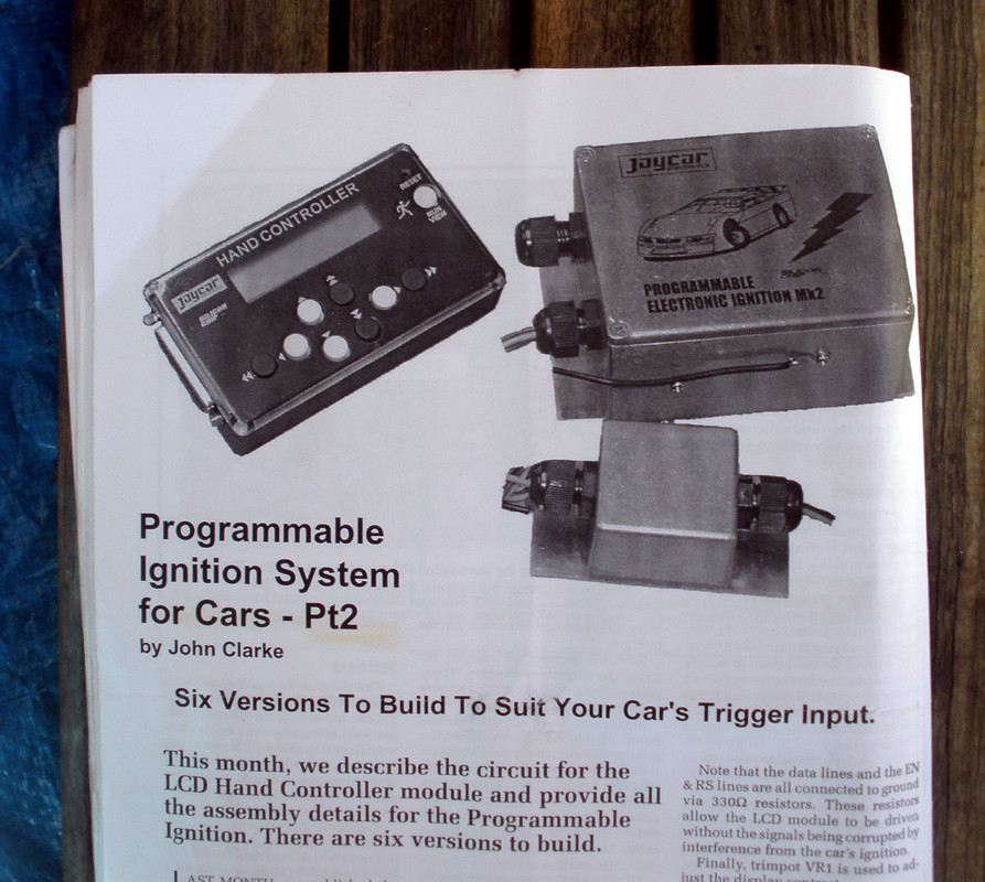 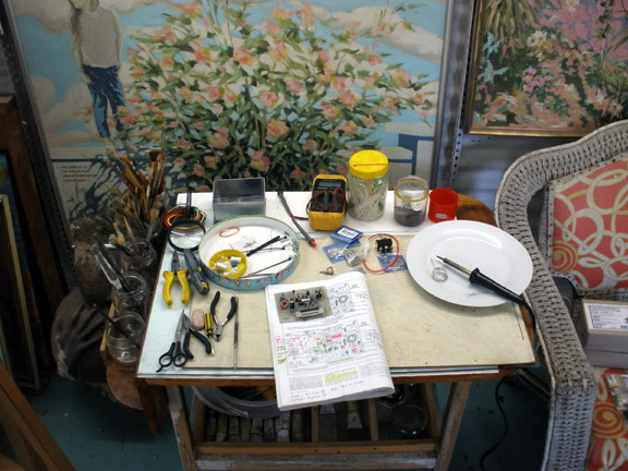 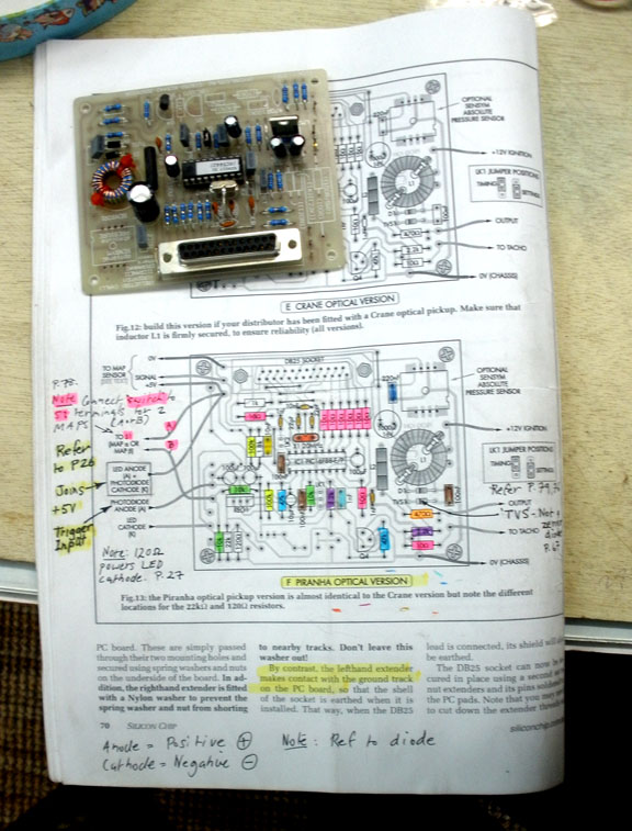 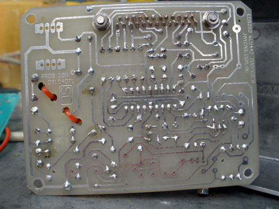 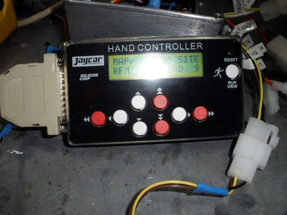 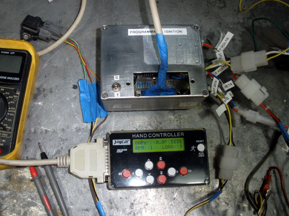 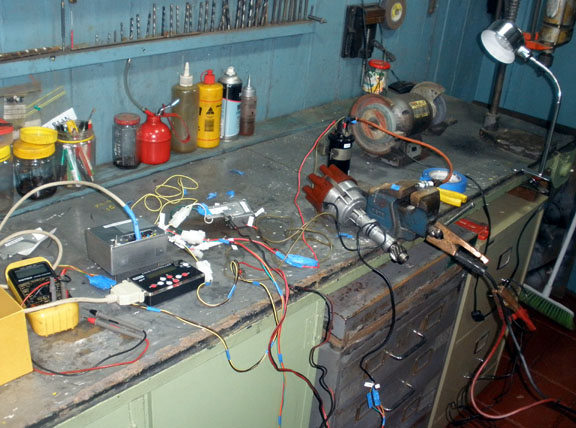 There's 3 major components for the assembly I'm using. The Programmable Module, the Coil Driver and the Hand Controller used for both programming and observing the engine status whilst it's running. I won't be using the 4th component, which is the Knock Sensor. The other component of course is the distributor which in my case utilizes the Pirhana optical trigger assembly. The kit includes a wiring diagram to connect this trigger mechanism to the module. Points triggering can also be used but you do have to lock up the advance mechanism totally. More to come....
|
|
|
|
Post by enigmas on Aug 30, 2016 8:03:43 GMT
Cont.... There's also been a lot of discussion about types of fuel, compression ratios, detonation/pinging/pinking of engines under certain conditions over the years on this forum. I'm not sure how familiar you guys are with ignition timing maps, but this may be of interest. 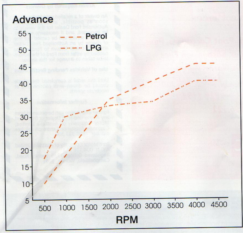 2 ignition curves.  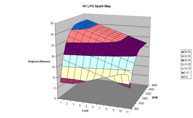 3D Ignition Map for a 6cyl VK Holden. 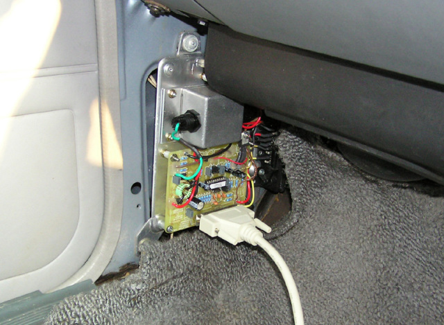 The Programmable module fitted to the interior kick panel of the Holden. 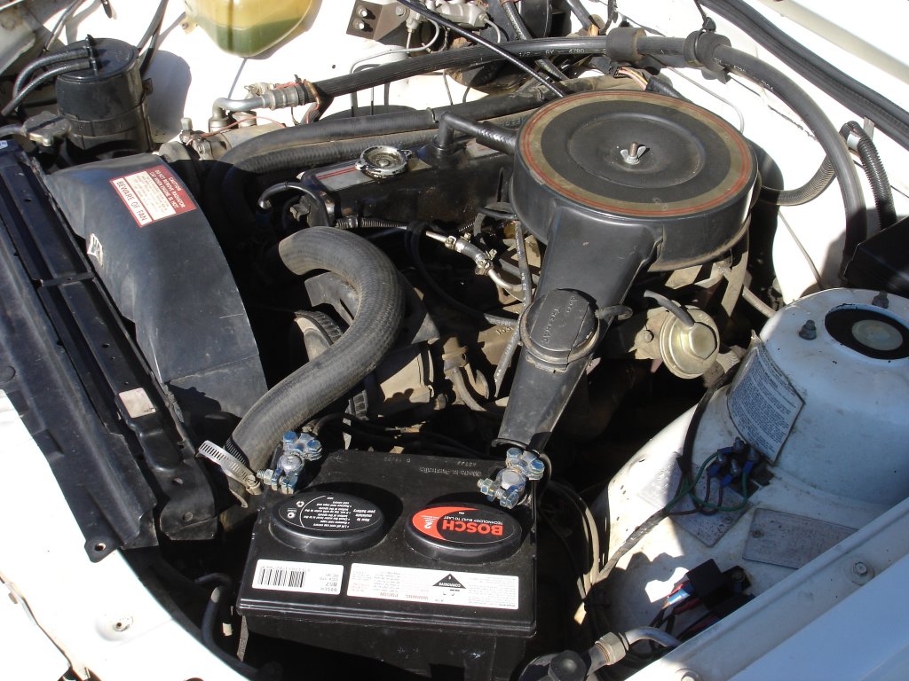 This is the engine of the VK Holden...carburettored and low tech. With regard to the 3D map (above)...notice how the graph folds back on itself. Programming the ignition curve like this enables the engine to speed up or maintain a consistent idle when extra loads are added at low engine speeds. Switching on the aircon or turning the powersteering adds load. When this load is sensed (reduced manifold vacuum) the ignition timing is automatically advanced which increases the engine speed. In the context of a Rover P5B engine that pings under load in certain road situations, the fix is to simply reduce the ignition advance at that particular load site. This is done by reducing some 'numbers' relating to degrees of advance at specific load points. If you look at the table below it's simply a matter of altering several parameters at the LOAD and RPM points where it occurs. Note: Load 1. Highest vacuum: Least engine load. (Idle or closed throttle descending a steep incline) Load 11. Lowest vacuum: Highest engine load. (Driving up a steep hill or towing a heavy load. Eg. Caravan) Your car tacho and any cheap car instrument vacuum gauge (if one is fitted to your car) will provide this info. 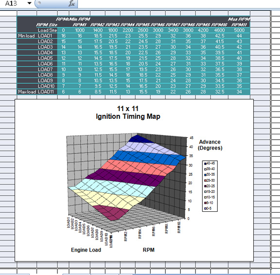 Ignition Timing Map for the Silicon Chip module. |
|
|
|
Post by enigmas on Aug 30, 2016 8:15:45 GMT
|
|
|
|
Post by enigmas on Aug 30, 2016 8:16:56 GMT
cont.... Below are 2 versions of the LPG ignition map. you can see that it's fairly comprehensive and in many ways quite straight forward. the first few maps that I designed were more complicated with very close increments between the load points but in reality it isn't required. The software within the program interpolates between the numbers where it's required so transitions are very smooth. The second graph shows the timing curve in 3D format. I'm not clever enough to have designed the 3D format but fortunately someone is. The XL spread sheet and the 3D graph are linked, so that the numbers entered into the various fields create the shape of the graph. This way you can see the curve as you design it. Looking at the graphs you can see that as load on the engine increases the timing is reduced...thus avoiding the dreaded pinging/detonation issues. If the motor were to ping at a particular RPM and LOAD point all that's required is to reduce the advance by a degree or so at that point till the pinging stops. Note also how all the numbers on the graph after 4600 RPM are zero! (These engines due to their longer stroke were redlined at 4400rpm originally, but obviously can be made to rev much more. Not a requisite for me) This is so that the motor can't be accidently over revved. It virtually acts as a rev limiter, killing the motor stone dead as the advance goes to zero. The engine in my car runs at 11:1 compression and even on LPG that's a lot! The beauty of the programmable ignition is that you can dial out the pinging. Try doing that with a mechanical system! 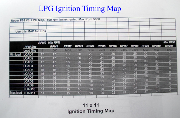 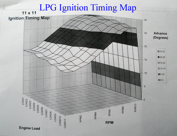 ISSUES: There were several self inflicted issues assembling the module. One was that I missed fitting a jumper link in the circuitry (merely a short piece of wire bridging 2 contacts) and also locating the correct lead to hook the controller to the module. I have the correct item now but ended up making one initially which I'm still using. The main issue was with the Pirhana Optical Trigger which for reasons unknown to me tends to have a delay of 10 degrees. For the Tech heads out there this is due to the Edge Triggering of the Module in relation to the Pirhana trigger. Simply put the module relies on the signal from the Pirhana trigger to start from TDC. It sees the signal as 0 degrees or TDC. What actually happens is that the module starts advancing from 10 degrees ATDC not at TDC. The easiest way to counter this is to either add 10 degrees to all the numbers in the timing map or simply advance the distributor 10 degrees physically. There are other ways to accomplish this electronically but this method worked for me and it was a simple fix in the end. As an side, I did get to know the designer John Clarke in a fashion, through a myriad of emails back and forth. He was very patient and helpful. I know from reading the literature that the design incorporates perhaps 6 - 7 different input triggers for the module, but I believe they were only ever run with mechanical points and electronic reluctor triggers by Silicon Chip. Here's a little video of the unit working in my car. If you look carefully there's a disconnected electrical white plug just above the coil. This is the lead from the Pirhana module which is still in place but can be hooked back to the distributor as both modules share the same plug. And that's the end of the Story! |
|
|
|
Post by djm16 on Aug 30, 2016 23:28:13 GMT
I am intrigued by the paintings and brushes in the first picture.
|
|
|
|
Post by enigmas on Aug 31, 2016 0:47:20 GMT
I have a fine art background and painted and exhibited for about 10 - 11 years when my children were young.
|
|
|
|
Post by enigmas on Sept 2, 2016 1:44:19 GMT
I've made another small YouTube video this time highlighting several small changes I've incorporated in the LPG ignition map. This one's a talkie boys, so enjoy!
|
|
|
|
Post by petervdvelde on Sept 2, 2016 22:31:39 GMT
Vince,
Interesting piece of equipment and nicely presented! It is a detailed way of controlling the ignition timing but you still have the rather rough way of fueling the system. Did you consider to use a Lambda sensor as a feedback system and make a more or less closed loop system?. I regretted that i didn't fit a Lambda sensor into my exhaust pipe of my MGB v8 conversion to do a rather easy check of how the engine runs.
Peter
|
|
|
|
Post by enigmas on Sept 2, 2016 23:12:56 GMT
Hi Peter, I have several options for fueling the engine. With regard to the programmable ignition module my intention is to have correct ignition maps for both types of fuel used. Modules that modify the petrol map on pre ECU controlled engines are a compromise, as load factors aren't included. This is why power is always down. (Refer to the fueling maps above)
Open loop LPG systems pass emission tests when setup correctly although this is not my focus. I do have a closed loop LPG module with a stepper motor that uses an oxygen sensor and have the appropriate bung welded into the exhaust manifold when I get around to fitting this stuff.
Petrol will always be a backup (emergency) fuel for my car if/when I find myself in the situation outlined in the opening comments of this post. Having said that, I do have a couple of intake manifold systems available, one being an early SD1 petrol EFI system. I've been collecting these parts for some time.
PS. Aldon Amethyst (UK) make a programmable ignition module with a very easy to use USB laptop interface for programming (and it's not a kit.) It's a very compact unit utilizing MAP load sensing and also includes the option for running 2 separate fueling maps. I also have one of these that will be fitted to my Magnette coupe project. They also have a library of fueling maps for various engines including the Rover V8. You'll probably have to write your own for LPG (or I can assist you with that if you go that way)
Both these electronic devices instantly improve the engine's operation. This is especially evident if it's a high compression unit and want to counter pinging/detonation without dismantling the engine.
|
|
|
|
Post by dave1800 on Jul 28, 2021 4:54:32 GMT
I appreciate that the thread is now several years old but I would like to say that I am very impressed with the description of how you built and installed the kit. I have I have recently been playing around with the Silicon Chip /Jaycar knock detection board and received some very helpful advice from John Clarke about how to calculate the component values to optimise the frequencies to suit a MGB engine - more in hope than expectation given the noisy rattly environment!
I was fascinated by your comment about the 10 degree delay using a Piranha ignition module as the trigger. I imagine you have already explored all possibilities for this given you have been so thorough but looking at your photos I wonder if the unit is possibly being triggered on the trailing rather than the leading edge of the slot? From some very crude measurements on the screen taken from your photo it appears that the trigger slot is around 10 degrees. I have built units using a hall sensor and not found a timing offset issue. I found it is not necessary to trigger at TDC but is easier to enter advance data without having to add or subtract an offset and it ensures the rotor arm alignment with the distributor cap terminals is not disturbed.
It would be interesting to know how the unit has fared if you have a free moment.
Thanks
David
|
|
|
|
Post by enigmas on Jul 28, 2021 12:47:27 GMT
Hi David, the module is still functioning flawlessly in my P5 coupe to this day (touch wood). Let me first clear any misapprehensions you may have about me as some kind of electronic guru, please excise that view from your mind. I'm sure I nearly drove John Clarke around the twist with my incessant quieries about some of the technical aspects of the module, but he did persist with me until I resolved the running issues I had with it. When interested in a project I tend to immerse myself in it totally, then after a period, forget about it totally. What I did find out was that the module was not capable of adding 15° - 20° of initial advance on an eight cylinder engine for LPG. LPG likes a lot of initial timing advance and much less than petrol at higher rpm. There simply wasn't enough time between firing intervals (on an 8 cyl engine) for the module to provide consistent and precise ignition control off idle with the amount of initial advance that I wanted to add. John designed the programmable module (something I can't even comprehend) but it's practical abilities AFAIK were only tested on a 4 cylinder car and certainly with no where as much lead timing as I wanted to introduce to the P76 V8 that motivates my coupe. Static timing on my locked distributor is set at 10° BTDC for LPG and the module adds 6° - 8° of timing to this depending on initial load. For petrol the timing map initially deducts timing and then slowly adds it back as required. The engine runs around 11:1 compression and doesn't ping at any load points as timing is deducted as required. The module's firing edge is set to Low not High. Switching to High Edge causes very erratic running with the Piranha optical trigger used in the distributor. Hope the info is of use to you. PS. David you really don't need the knock sensor. The heart shaped combustion chamber is the likely cause of the "knock". This is due to the sharp peak of the chamber. Radiusing the peak downwards into the roof of the chamber will negate the peak's likelihood of pre-igniting the fuel air charge. It's simply a bad piece of design especially on a freshly faced cyl head. A mechanic who has expertise with these B series engines would know this. Definitely not on the radar of any today's keyboard mechanics. The peak will get hot enough to light up the air/fuel charge. Radiusing it fixes this issue. I can provide an image/instructions if needed. Other than this, simply load the engine until you hear the knock, note the RPM at which it occurs, then remove a couple of degrees at this RPM/load point with the hand controller. Test again, if the knock is no longer evident...the job's done. Otherwise remove another couple of degrees. That's the primary benefit of the programmable module, the ease of altering the advance curve to suit the particular requirements of the engine  👍 |
|
|
|
Post by dave1800 on Jul 29, 2021 3:15:54 GMT
Many thanks. It is good to know that the unit has proven to be reliable and is a testimony to your kit building skills and John Clarke’s design.
There is one quick check you may find helpful and that is to measure the stability of the 5V regulator output. The LM2940 regulator is very sensitive to the effective internal resistance (ESR) of the electrolytic capacitors on its output. If they degrade with time this can cause problems that I imagine would show up with the PIC possibly rebooting or even damage from over voltage. As you have mounted your unit away from the engine bay hopefully this won’t be an issue.
The issues you encountered are interesting. I believe the vehicle John used to test the unit was a 4 cylinder Ford Telstar as there is a sample map for this vehicle in the PIC program assembly file.
I would have expected the normal trigger arrangement for the Piranha output to go high. I have read of an issue with an Aldon Amethyst that would only work if the trigger position was set some way from the firing point presumably because of feedback inside the distributor. I think this was with a reluctor pickup and these can be quite sensitive. I notice you have clearly identified the need to keep the coil feed wires away from the trigger.
My experimenting with the knock detector is more out of curiosity to see whether it can be accurately detected above the background engine noise. As you point out the BMC B series cylinder heads have hot spots that can be improved and I do have the details but thank you for your kind offer.
David
|
|
|
|
Post by enigmas on Jul 29, 2021 9:22:39 GMT
What compression ratio is the engine running David?
|
|
|
|
Post by dave1800 on Jul 29, 2021 12:03:11 GMT
Nothing fancy 9:1. Knock isn't really an issue but I would like to try advancing the timing to find the sweet spots while limiting the risk of damage.
Going back to your comments about the unit not being able to add the 15-20 degrees off idle for initial advance for LPG on an 8 cylinder engine is a little strange. As this additional advance seems to only be required up to around 1500 rpm where the time available between pulses to carry out the calculations is twice that at 3000 rpm where you clearly have no problems. The specifications suggest that it is possible to adjust the timing adjustment range up to +/-90 degrees for an 8 cylinder engine (although no more than 75% of this is recommended). The MGB has ported vacuum take off so it quickly adds around 10 degrees of advance as the throttle is opened.
There is, however, part of the program that compensates for the response to low RPM that tries to prevent the timing from being retarded when you accelerate primarily from low rpm. You will recall this is one of the criteria you need to determine in the settings. I have no idea how this works and a programmer friend who uses PIC micros hasn't been able to come up with an answer yet. In theory an 8 cylinder engine should be less prone to problems with the response to low rpm than a 4 cylinder as there is less time between pulses for the engine speed to change.
You clearly have a good working solution to the issue which is great.
David
|
|
|
|
Post by enigmas on Jul 29, 2021 14:45:52 GMT
I've simply worked my way around issues that I initially found with the module when I started to write ignition timing maps for the V8 on LPG. Essentially trial and error until I refined one that I felt worked best with the engine. I must have modified at least a dozen MAPS from the one I initially started with.
I still believe based upon my observations (of the engine's response) that the module can't accommodate large amounts of advance (15° - 20°) straight up after starting just above cranking speed (approx 350 rpm.)
Once above idle speed (750 rpm), the module only needs to deal with with relatively small increments of advance. The 10° BTDC static timing setup with the locked distributor, from my reading, just removes some of the computing load off the module.
* Response to Low RPM Setting (Source: Programmable Module Build Booklet. From the kit)
" At low RPM the engine speed can change quite quickly. Because the calculation for RPM can only occur between each detected firing pulse, the response to RPM changes can be too slow and lag behind the engine. This can noticeably retard the ignition with increasing RPM."
I'll post a copy of the most current LPG ignition timing MAP tomorrow for interest once I locate my notes.
|
|
|
|
Post by enigmas on Jul 29, 2021 15:06:10 GMT
Nothing fancy 9:1. Knock isn't really an issue but I would like to try advancing the timing to find the sweet spots while limiting the risk of damage. The MGB has ported vacuum take off so it quickly adds around 10 degrees of advance as the throttle is opened. David 'Ported Vacuum' occurs in front of the throttle blade and only really activates fully when the engine is buzzing around cruising rpm...perhaps 2500 rpm or the engine's point of maximum torque. It's primary function is to improve combustion and fuel economy during steady state cruise conditions when the mixture leans off. Manifold Vacuum is created behind the throttle blade and drops off once the throttle is opened but will act instantly in a closed throttle situation. Ported vacuum won't add advance quickly as the throttle is opened, you'll have to hold the rpms up around 2500 rpm and steady to show a stable held increase in advance. Here's a good link on the subject if interested. chevellestuff.net/tech/articles/vacuum/port_or_manifold.htm |
|
|
|
Post by dave1800 on Jul 30, 2021 2:17:31 GMT
I have read the article in the link and here are my observations over many years with a B series engine fitted with SU carb(s). The ported vacuum on the MGB can add up to 20 degrees of advance, depending on the distributor, and this begins as soon as the throttle starts to open. I think it is important to differentiate between the rpm for a given throttle opening under no load with the vehicle stationary and under load when driving. The later US spec vehicles used manifold vacuum advance typically giving around 10 degrees more advance at idle. This was part of the emission modifications - and made cranking harder. Over around 1200 rpm both systems achieve the same combination of mechanical and vacuum advance. The rapid increase in vacuum advance with the ported system as the butterfly opens is essential for a smooth take off. Unlike the examples in the article the MGB static timing is set around 10 degrees BTDC not 4 or less.
In practice the ported system will increase the engine temperature at idle but this has not proved an issue apart from the Austin Three Litre that I believe moved to manifold take off. (Please see my additional comments on the response to low rpm).
David
|
|
|
|
Post by dave1800 on Jul 30, 2021 2:34:03 GMT
I wonder if your observations about the inability of the module to provide 15° - 20° of advance immediately after starting just above cranking speed relates to the way in which the software handles the response to low RPM setting?
Although as I previously mentioned I do not properly understand how this is being achieved I can only assume that it must involve additional calculations that will take additional processing time. It may be that the compensating corrections at low RPM conflict with the ability to add the advance.
This is pure speculation on my part but I will ask my programmer friend to look at this again. I don’t think it fair to bother John as the article was originally published in 2007 in Silicon Chip Magazine and a couple of years later in EPE in the UK.
I look forward to seeing a copy of your LPG MAP.
David
|
|
|
|
Post by enigmas on Jul 30, 2021 9:38:39 GMT
I don't think John would mind if you queried him over the matter, as he'd probably also like to know. He's very approachable. I think the real issues stems from the lack of extensive hands-on' practical' testing on a range of engine configurations...not just inline 4 cyl engines. It truly is not an issue for me David. My work-around method suffices for what I want from the module, which is primarily 2 viable ignition maps. As I stated previously, it is very reliable as currently setup. Just in case you're wondering, none of this was a weekend exercise. I spent several months tooling about with various ignition timing maps, isolating specific wiring and also making mechanical adjustments to how the timing was introduced. Having finally sorted it to my requirements for the car, I'm not about to attempt any more reconfiguration. If you have the kit at hand, go for it. Writing up an ignition map for petrol is no big deal. 👍 |
|
|
|
Post by enigmas on Jul 30, 2021 10:25:51 GMT
I have read the article in the link and here are my observations over many years with a B series engine fitted with SU carb(s). The ported vacuum on the MGB can add up to 20 degrees of advance, depending on the distributor, and this begins as soon as the throttle starts to open. I think it is important to differentiate between the rpm for a given throttle opening under no load with the vehicle stationary and under load when driving. The later US spec vehicles used manifold vacuum advance typically giving around 10 degrees more advance at idle. This was part of the emission modifications - and made cranking harder. Over around 1200 rpm both systems achieve the same combination of mechanical and vacuum advance. The rapid increase in vacuum advance with the ported system as the butterfly opens is essential for a smooth take off. Unlike the examples in the article the MGB static timing is set around 10 degrees BTDC not 4 or less. In practice the ported system will increase the engine temperature at idle but this has not proved an issue apart from the Austin Three Litre that I believe moved to manifold take off. (Please see my additional comments on the response to low rpm). David I can't agree with your version of ported vacuum David. Ported vacuum is in front of the butterfly or between the butterfly and air filter. It simply can't add much additional advance (certainly nothing like 10°) at idle speed as there's insufficient airflow over the port. I've never known increased advance at idle to increase engine temperature either, but certainly, late static ignition timing tends to heat the engine block and coolant. If the vacuum capsule on a distributor is attached to manifold vacuum (not ported vacuum) and the initial static timing is say at 4° BTDC the engine should fire up relatively easily 'at cranking speed' before manifold vacuum is added when the engine starts. Then the centrifugal advance takes over if setup with light springs. I alway set the static ignition timing on my engines using a vacuum gauge and remove advance at the other end of the curve if required even when using a mechanical advance distributor. This can be done using a schoolboy's plastic protractor. If you drive an automatic it'll provide the greatest punch off idle. A hot running, idling engine (with a viable cooling system) can be brought down in temperature by advancing the timing. Late combustion cycles just heat the block. |
|
|
|
Post by dave1800 on Jul 30, 2021 10:52:51 GMT
I appreciate all of the effort you have made to build and install the unit to such a high standard. I know from personal experience just how much is involved and my projects always take me at least twice as long as planned even when there is no additional complexity such as plotting ignition advance curves. Sorry if I gave the impression that I was suggesting you make changes to a working set up which was never my intention or something I would do! I was just trying to understand the limitations you described.
I keep going back to the issue of the correction for low RPM and the three references in the article are a little confusing:-
"Response to low RPM setting: 0 to 25,500 RPM in 100 RPM steps. Typically set at around 1000 to 2000 RPM."
"Usually the setting is adjusted so it operates at engine cranking speed but stops when the engine reaches idle speed. In other cases it may be necessary to raise this RPM limit so that the engine can rev correctly from idle."
"Additionally the response to low RPM setting may need to be increased to a few hundred RPM above the idle speed for best “take-off” acceleration."
I think it boils down to just finding out what is best for your engine through trial and error!
I do have the Jaycar kit and have designed an add on circuit that should enable it to feed a wasted spark coil with two crankshaft triggers to be able to omit distributor and associated drive issues (it uses two ignition driver units). Probably a bit over ambitious but is something I would like to try.
I will contact John as you suggest to see if he can clarify the problem you encountered with not being able to add the advance immediately above cranking and throw some light on the low RPM calculations.
Thanks for your help
David
|
|
|
|
Post by dave1800 on Jul 30, 2021 11:11:32 GMT
I have read the article in the link and here are my observations over many years with a B series engine fitted with SU carb(s). The ported vacuum on the MGB can add up to 20 degrees of advance, depending on the distributor, and this begins as soon as the throttle starts to open. I think it is important to differentiate between the rpm for a given throttle opening under no load with the vehicle stationary and under load when driving. The later US spec vehicles used manifold vacuum advance typically giving around 10 degrees more advance at idle. This was part of the emission modifications - and made cranking harder. Over around 1200 rpm both systems achieve the same combination of mechanical and vacuum advance. The rapid increase in vacuum advance with the ported system as the butterfly opens is essential for a smooth take off. Unlike the examples in the article the MGB static timing is set around 10 degrees BTDC not 4 or less. In practice the ported system will increase the engine temperature at idle but this has not proved an issue apart from the Austin Three Litre that I believe moved to manifold take off. (Please see my additional comments on the response to low rpm). David I can't agree with your version of ported vacuum David. Ported vacuum is in front of the butterfly or between the butterfly and air filter. It simply can't add much additional advance (certainly nothing like 10°) at idle speed as there's insufficient airflow over the port. I've never known increased advance at idle to increase engine temperature either, but certainly, late static ignition timing tends to heat the engine block and coolant. If the vacuum capsule on a distributor is attached to manifold vacuum (not ported vacuum) and the initial static timing is say at 4° BTDC the engine should fire up relatively easily 'at cranking speed' before manifold vacuum is added when the engine starts. Then the centrifugal advance takes over if setup with light springs. I alway set the static ignition timing on my engines using a vacuum gauge and remove advance at the other end of the curve if required even when using a mechanical advance distributor. This can be done using a schoolboy's plastic protractor. If you drive an automatic it'll provide the greatest punch off idle. A hot running, idling engine (with a viable cooling system) can be brought down in temperature by advancing the timing. Late combustion cycles just heat the block. I think you are correct the 40897 early MGB distributor (claimed by some as the best) produces around 10 degrees of vacuum advance at around 8" Hg which is going to be at higher RPM than the 1200 I quoted. In fact this distributor advances the timing mechanically by around 9 degrees from an (optimistic) idle of 700 RPM to 1600 RPM. An issue sometimes quoted on US MGB websites is that the manifold vacuum advance at idle is affected by the pulsing resulting from the inlet siamese port arrangement but I have no experience of this. David |
|
|
|
Post by enigmas on Jul 30, 2021 11:21:58 GMT
Here's the most current LPG ignition map that I'm using in the module David. 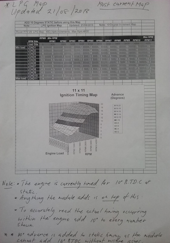 |
|
|
|
Post by dave1800 on Jul 30, 2021 12:11:36 GMT
Thanks.
|
|
|
|
Post by enigmas on Jul 30, 2021 14:04:19 GMT
I really don't believe you'll have any issues configuring the module to run a viable petrol ignition map with your MGB David. John Clarke is obviously a wiz at designing electronic devices but the writing leaves a lot to be desired from a communication point of view. Not the technical stuff if you comprehend it, moreso some of the explanations for configuring certain specific settings, such as the 'Response to Low RPM Setting' that you've highlighted. A lot of the design and project build articles for this module were built on top of previous and simpler electronic ignition kits several of which I've built and still have running in my other classics. I don't pretend to understand the workings or even the inter-relationship of some of the components but do manage to assemble the kits successfully (touch wood.) The configuring part, with several quite confusing settings is really a trial/error/elimination process until the correct values are realized. Most of that being based on knowing the difference between a smooth running engine and one battling itself. So although all the theory behind the electronics of the module may make perfect sense, if you don't have a feel for how an internal combustion engine behaves under stress, then it's all purely academic. (~ Vince) |
|


 👍
👍