|
|
Post by petervdvelde on Sept 24, 2016 22:01:46 GMT
The engine was removed from the car. Everything went rather smooth, no broken or rusted solid bolt or nuts.
After removing the BW35, the ZF starter ring gear plate, adapter and flex plate were fitted and bolts were fitted with Loctite and with the right torque. The information was received by mail from Andy.
A new torque converter came with the ZF4 box
The box was fitted to the engine
First issue to solve was the kick down cable.
The picture above shows the original bracket and the (Jaguar) ZF4 kick down cable. The diameter of the threaded part of the ZF4 box was thicker and longer and especially the increased length made it impossible to fit.
I also found out that the stroke of the KD cable of the BW box is approx. 25% bigger than the one on the ZF box so i also modified the bracket arm because otherwise the throttle would be limited by the KD cable. Underneath a picture of the modified bracker and arm.
This ZF4 HP22 is from an LDV which has the advantage of having a mechanical speedo. Most other boxes have an electronical speedo.
The disadvantage of the LDV box is that is a fair bit longer so the bracket on the rear subframe leg has to removed
This is the original bracket
which was grinded off
A new bracket was made which was more or less identical to the original one but facing to the rear. I didn't make a picture.
The engine with ZF4 box were trial fitted
Underneath a picture taken from the underside which shows the mounting bracket set up. The original mounting rubber was used
It all needs to cleaned up. The welds are that nice and laying underneath the car and welding above myself isn't a favorite job.
Also a shortened propshaft was fitted
ext step is to add some weld and clean it all up and then i will have a look at the shifting mechanism.
The BW35 has a system with rods and the ZF4 uses a cable.
Thats it for now
Peter
|
|
|
|
Post by wozzer on Sept 25, 2016 7:17:25 GMT
You certainly know your stuff peter well done on the seats which are looking very nice.
Gearbox is a great mod you nust let us know how they perform.
|
|
|
|
Post by enigmas on Sept 25, 2016 10:45:36 GMT
Looking good Peter. It's very useful to see the initial work. I've got a Range Rover ZF sitting under the house, but still need a few components to modify it for 2 wheel drive. I'll definitely bookmark this post.
|
|
|
|
Post by petervdvelde on Sept 29, 2016 18:57:09 GMT
You certainly know your stuff peter well done on the seats which are looking very nice. Gearbox is a great mod you nust let us know how they perform. Thanks Woz. Have great expectation from this ZF box. I was happy with how the BW35 shifted but the RPM was too high when driving 110-120 km/hr Vince, Andy is the specialist when it comes to box setup. I understand that the LDV box is longer than a combined RR/Jaguar box and it will be difficult to find a tail piece with an mechanical speedo. I understood that certain Peugeots (505 or 605) had these but these cars have become rare. After some considerations and discussions, i decided to let the shifter cable run to the front of the car. This was done because the shifter cable can be adjusted easier. A bracket was made which is mounted onto the shifter [ The cable is a Jaguar cable and because the cable end is a solid rod which cannot follow the circular movement of the Rover shifter, the outer cable connection was made that it can rotate. I had a look at a Jaguar shifter and saw that the cable end runs a straight line. The end piece of the shifter rod was replaced by a clevis. An inspection hole will be cut into the transmission tunner cover so that the cable can be adjusted. Here a picture of the connection on the ZF box With the current setup the shifter can reach all 7 positions of the ZF box. In the upper part of the Rover shifter, there is a kind of position locking system, which is not totally usefull for the ZF box. I also have a LDV shifter so can see the differences. Andy already had a look at this and offered to share his knowledge. Thats it for now Peter |
|
|
|
Post by john68saloon on Oct 1, 2016 16:07:37 GMT
I've just done the same conversion to my saloon but I am sure that the kickdown cable on the ZF is supposed to release when the throttle is opened. If not then I've done mine wrong?
I've not tried it properly yet on the road but my donor box came with an engine from a Sherpa complete with the inlet manifold and it was set up for the kickdown cable to be under tension with the throttle closed and then releases the cable as the throttle linkage opens. John
|
|
|
|
Post by petervdvelde on Oct 2, 2016 11:51:05 GMT
Hello John,
I believe the the KD cable should be a "pull" movement. I have another P5B which is a long term restoration project.
This P5B also gets the LDV box which o already have and with this box i bought the inletmanifold which i will use as i like the later SU better. I already restored this manifold but haven't fitted the KD cable.
I had a look at the manifold and at the brackets and see what you mean
Here's a picture of the manifold
If the KD cable is fitted next to the throttle cable on the same bracket then i see what you mean.
Maybe Andy can advice us.
Peter
|
|
|
|
Post by gingerbeer62 on Oct 2, 2016 15:07:00 GMT
Hello John, I believe the the KD cable should be a "pull" movement. I have another P5B which is a long term restoration project. This P5B also gets the LDV box which o already have and with this box i bought the inletmanifold which i will use as i like the later SU better. I already restored this manifold but haven't fitted the KD cable. I had a look at the manifold and at the brackets and see what you mean Here's a picture of the manifold 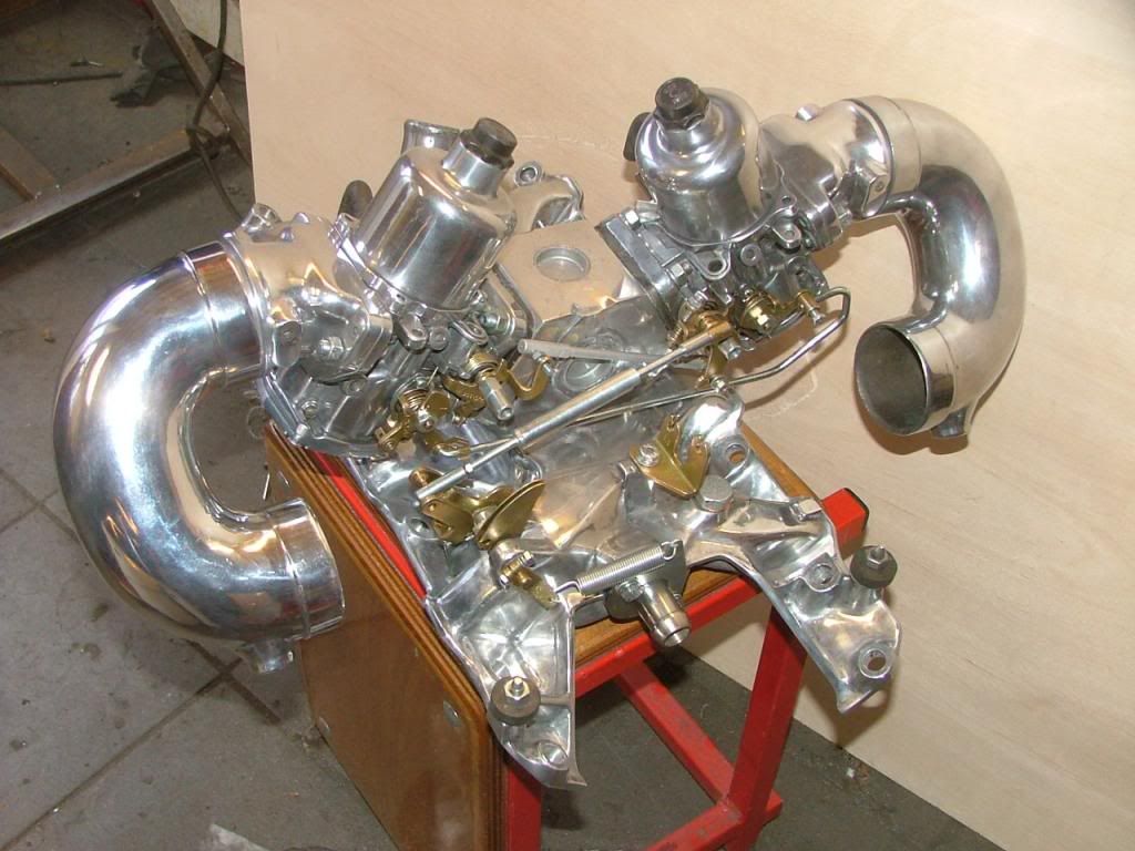 If the KD cable is fitted next to the throttle cable on the same bracket then i see what you mean. Maybe Andy can advice us. Peter No, this is not a picture of a manifold - it is a picture of a work of art !! Outstanding work ! Cheers Colin |
|
|
|
Post by eightofthem (Andy) on Oct 2, 2016 18:50:52 GMT
Hello John, I believe the the KD cable should be a "pull" movement. I have another P5B which is a long term restoration project. This P5B also gets the LDV box which o already have and with this box i bought the inletmanifold which i will use as i like the later SU better. I already restored this manifold but haven't fitted the KD cable. I had a look at the manifold and at the brackets and see what you mean Here's a picture of the manifold If the KD cable is fitted next to the throttle cable on the same bracket then i see what you mean. Maybe Andy can advice us. Peter It does look very good Peter. I guess the throttle cable is attached to the half moon bracket closest to the rear, so the K/D cable should be attached to the lever arm that points upwards and to the 11 o clock position. There should be a clip that attaches to one of the inlet manifold bolts that supports the adjuster end of the K/ D cable. I think I have one here, I will post up a picture when I find it. I also have a set of those carbs should anyone need them. |
|
|
|
Post by john68saloon on Oct 2, 2016 23:16:52 GMT
Yes I have the same manifold and carbs as yours although I'm not using them on my p5 at the moment.I've looked several times at mine and I can only see that the cable should release when the pedal is presse. I have driven mine only a short distance so far as it is not mot tested yet but the gears seem to change fine with the cable releasing rather than pulling. I'm confused though because the info I've found on range rover forums contradicts this way of setting it up. John
|
|
|
|
Post by enigmas on Oct 3, 2016 0:05:59 GMT
Hi John, I think the responses todate have all missed the focus of your question and bypassed your query! I believe your query is (but could be wrong!), does pulling on the trans cable increase the transmission system pressure or reduce it? I've got a ZF transmission tucked away under the house and could possibly retrieve it, remove the sump to check the operation of the valve, but don't believe this is necesary. The link below should clarify your query. gershon.ucoz.com/ZF/powertrain-zf.pdfI. 1.7 Throttle Valve Mechanism (kick-down) The throttlevalve or 'kick-down' mechanism comprises a cable connected between throttle body pedal and the throttle valve cam/ quadrant located on the selector valve shaft; the cam operates the throttle valve housed within the throttle valve block. The travel of the valve is proportional to throttle positions and alters shift speeds and pressures during gearshifts to take account of throttle position. The mechanism also provides for immediate selection of a lower ratio (eg when overtaking) by depressing the accelerator beyond the normal full-throttle position. 'Kick-down' is operated by movement of the throttle cable into the 'kick-down' position causing full movement of the throttle valve and directing oil flow to the shift valves. NB. Since the valve movement is proportional to throttle position pulling the cable (not releasing it) it increases system pressure. Moving on... PS. Nice bit of 'bling' on the manifold Peter. |
|
|
|
Post by john68saloon on Oct 3, 2016 8:05:12 GMT
Thanks for the replies. I'm going to flip the cable over and try it. Looking how mine is, it doesn't look right and every other auto I've been involved with doesn't work this way.
|
|
|
|
Post by enigmas on Oct 3, 2016 8:44:20 GMT
What automatics John? Every version of a BW35, 40, 50 and 65 operate on the same principle. Others with vacuum modulators obviously use a different method of load sensing!
|
|
|
|
Post by john68saloon on Oct 3, 2016 13:52:41 GMT
Hi, yes I know from setting up my BW35 in my Triumph and the Alison AT545 boxes in our old buses that the cable pulls to work. What I was implying was that I believed that the ZF worked differently looking at the manifold and the linkages I have.
Today I have changed the linkage on the Rover so that it pulls, using a cable bracket from a Range Rover fitted to the L/H rocker cover.
I can confirm that this is now the right way to do it.
So sorry that I may have caused any confusion.
The gear change is sweet now and when Drive is selected there is no thump. In fact it can hardly be felt selecting D or R.
John
|
|
|
|
Post by john68saloon on Oct 3, 2016 13:59:24 GMT
Peter, your gear selector set is very neat too. I did mine the lazy way and made a rod from the bottom of the Rover selector straight to the gearbox. It all seems to work fine and I have P,D,N,R all in the correct position.
Many thanks to Enigmas for the kickdown cable help.
|
|
|
|
Post by vincentacres on Oct 4, 2016 5:11:28 GMT
I did mine the same way by cutting and welding the rod to achieve the right length and by extension the screw in bolt in the bottom of the gear selector in order to achieve a longer throw/correct arc.
As far as the lockouts etc. go I dismantled the selector from a Range Rover with a ZF box and removed these parts for comparison. They are upside down compared to the Rover but still serve as a useful reference. I have found so far though after 5,000kms with the ZF box that I haven't needed the modified lockouts.
I think Peters work will produce a superior product but the rod method works and is easy to install and also preserves the original shifter.
For the gearbox mount I adapted a BMW mount which is working well and was simple to install.
Owen.
|
|
|
|
Post by petervdvelde on Oct 4, 2016 5:52:51 GMT
Peter
[/quote]No, this is not a picture of a manifold - it is a picture of a work of art !!
Outstanding work !
Cheers
Colin
[/quote]
Thanks Colin
|
|
|
|
Post by petervdvelde on Oct 4, 2016 6:07:33 GMT
Thanks Vince and Andy for your valuable comments.
John, Owen,
I also thought about making a rod for the shifter but on the original BW set up there is an additional rod and a plastic bracket which compensates for relative movements, (caused by the subframe silentblocks) between box and shifter. I don't know how big these movements can be so i didn't want to take the risk but Owen's test miles prove that it can work.
The thing i still need to do is the transmission cooler. I will install a separate cooler. What did you do? Did you use pipes (cupper or steel?), hoses or a combination?. Where did you get the nipples from? I found these with professional hydraulic compagny's but not all want to deal with a private person needing only a few nipples. Maybe a company who deals with old Jags could supply these.
Peter
|
|
|
|
Post by john68saloon on Oct 4, 2016 9:28:52 GMT
Peter, I bought an oil cooler from ebay new for £28, I used the pipes from the sherpa which I modified to fit the Rover. On the ends I used some hose bought from a local hydraulic supplier and clamped them on with those little clamps that you crimp up both sides.
The cooler is mounted up in front of the radiator now
|
|
|
|
Post by vincentacres on Oct 5, 2016 3:45:13 GMT
Gents, I followed the same path - a seperate cooler mounted in front of the radiator with hoses and clamps between the ZF metal pipes, the bw35 pipes and the cooler. My understanding is the oil circulates at low pressure so I was not too concerned about the fittings themselves. From memory though I had to run one pipe under the ZF so I reinforced and protected this with some sheathing.
|
|
|
|
Post by petervdvelde on Oct 5, 2016 7:22:29 GMT
Thanks for the reply's. I don't have the LDV popes so will look for another solution.
Owen, is the car ready now? I remember seeing some picture of a very nice subframe with engine ect. I and more forum visitors would be interested to see a bit more of your car.
Peter
|
|
|
|
Post by petervdvelde on Oct 5, 2016 21:05:35 GMT
Finished the bracket on the box, made a coverplate for the inspection opening and modified the arm on the box to a clevis.
The smaller parts were shot blasted and the larger parts cleaned with a rotating wire brush
and spray painted with primer and topcoat
Then the shifter locking pattern was made. First welded up two of the locking plate and cut a half moon piece out of a spare shifter
[
Fitting these welded up plates to the shifter and connecting this to the shifter cable gives a good view of where the locking grooves need to be made
After running threw all the gears and marking these on the welded up plates and making the grooves gave this result and some differences to the original plate can be found.
There is not much room for the 1,2 and 3 position so i reduced the ends of the pin which runs threw the shifter from 3,5 to 3 mm.
It now gives very precise and secure shifts for D,N,R and P. The 1,2 and 3 position is a little less precise but these are hardly used.
Thats it for now
Peter
|
|
|
|
Post by Phil Nottingham on Oct 5, 2016 21:30:22 GMT
Your attention to detail is never ending  |
|
|
|
Post by petervdvelde on Oct 12, 2016 20:55:57 GMT
Thanks Phil,
Engine and ZF box are back into the car. Andy supplied the ZF box with a Jaguar sump which give a bit more groundclearance.
The dipstip is connected to the sump and on the LH side. The LDV and Range Rover dipstick are on the RH side.
With a little bending the Jaguar dipstick tube could be fitted.
A bracket was made to fit the oil cooler in front of the radiator. It seems it is better to leave as much room as possible between oil cooler and radiator. The oil cooler was fitted with rubbers to the bracket.
I bought some steel hydraulic 12mm pipe. This is thick wall pipe and not easy to bend. Couldn't find/borrow a suitable bending tool which can make bends close to each other so made my own bender using two large innerrings from old ball bearings.
The bender works well can makes tight bends. The pipes will be connected to 2 short hoses which will be connected with pipes which run along the engine to the box. Connection to the box will be done with banjo bolts connected to hoses. Have to make the second set of pipes.
Peter
|
|
|
|
Post by petervdvelde on Oct 18, 2016 21:37:58 GMT
As there is insufficient room on the LH side near the bell housing due to the filler tube and the exhaust y- piece, i decided to route the pipes near the the RH side.
Here the routing behind the radiator
[
I had some hoses made. The company is specialized in high pressure industrial hydraulic so the hoses can hold 380 bars and are rather thick.
More pictures were made from the piping underneath the car but space is limited so not good enough to post. The connections with the ZF box were made with hoses and Banjo bolts
Speedocable and electrical connection were done and the shifter was fitted. Although the curves the shifter cable make are tight, the shifter shift easy and very precise.
The installation of the ZF box is ready now. Need to fit coolant hoses, PAS hoses, choke and accelerator cables and fill up all the liquids and then can test the car
Peter
|
|
|
|
Post by johnwp5bcoupe on Oct 19, 2016 8:33:29 GMT
You seem to have gone a bit over the top with the Hydraulic hoses Peter if its the same pressure as the BW35 it's sub 40psi! But a nice job |
|