|
|
Post by djm16 on Jul 25, 2023 8:53:07 GMT
I call it correcting, as 2 o or 1 1/2 o of positive camber is pretty hard on modern tyres, particularly the LT tyres I have on now (all that you can get for a 3-litre that is suitable in Australia). Of course, enthusiastic cornering might be contributing to the excessive outside edge wear. Too much toe-in would do it, but in my case toe-in is as close to zero as I can estimate on multiple measurements. A local person (to Perth WA) has been modifying the link mounting pin housing (17) by blinding the fixing holes and re-drilling them 3mm inwards so that the bottom link sits 3mm further out. A quick calculation predicts that this will still leave a lot of positive camber. But 3mm is absolutely as far as you can go before the fixing bolts break into the side of the bushes etc. The inboard pivot on the top link and bottom link sit close enough to 300mm apart, one above the other. So to take out 2o o camber, we would have to move the bottom link out by 300 x sin(2o) mm, which comes to near enough 11mm. Even 1 1/2o camber is near enough 8 mm on the bottom link. The other practical option is to modify the top link. I know enigmas has done this to correct castor by cutting and welding shut. I am not sure I would trust my welding skills on such a crucial component, but it did occur to me to move the top ball swivel mounting holes by welding shut and re-drilling them. Has anyone else considered that? The additional advantage is that removing the top links is much easier than getting to the link mounting pin housing.
|
|
|
|
Post by enigmas on Jul 25, 2023 11:18:28 GMT
The secret to a strong weld David is to ensure that there is good penetration into the parent metal. Quality Gas MIG welders are very reasonably priced these days. Consider that you are welding quite heavy section steel 1/8" - 3/16" on some sections of the upper wishbones. It's the thin stuff that really requires a patient approach and lot of finesse. Cut and then bevel the sections you want to weld together. Weld into the valley and then lay several beads on either side to build the weld into the parent steel. Turn up the settings on the machine and practice on some quarter inch scrap. With the correct settings and a controlled steady hand the welds will be super strong and meld with the parent metal. On your practice pieces cut through them with a slitting disc and assess the penetration. If carried out properly and from both sides all the parent metal will have merged with the weld. I made a simple jig out of sections of hardwood decking timber (which I still have aside) for modifying the caster angle on the upper wishbones. There's really nothing stopping you from doing the same. By cutting and moving the sections both inwards and back you can incorporate both negative camber and positive caster. The amount of alteration to both these front suspension steering angles is down to how carefully you design the jig. This link may assist your deliberations. roverp5.proboards.com/thread/12128/mikes-loon-saloon?page=8 |
|
|
|
Post by djm16 on Jul 26, 2023 2:11:53 GMT
Thanks for the advice. I recall your article from before and applaud your patience and skill. As I was not planning on varying the castor, only the camber, moving the mounting holes seemed the least invasive ploy.
|
|
|
|
Post by enigmas on Aug 4, 2023 1:52:10 GMT
This wheel alignment sheet from Mike Hancock's P5B coupe "Winston" may provide some useful tech data for anyone unfamiliar with the standard "fixed" factory settings. 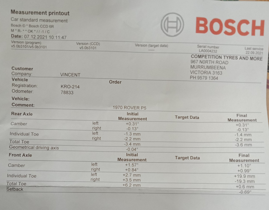 |
|
|
|
Post by flatplane8 on Aug 14, 2023 21:29:51 GMT
Hi,
i re-bushed my front suspension many years ago. I got some nylon bushes made with the pin holes offset. This allowed me to get some negative camber without having to cut and weld anything.I also replaced the subframe bushes with solid discs to lower the body, this had the side effect of increasing the castor a bit.
Simon
|
|
|
|
Post by enigmas on Aug 15, 2023 8:02:40 GMT
Although not directly related to the RoverP5s front suspension's camber geometry, Simon's comment above with regard to the front suspension subframe bushes and their current condition should be taken into account. Here's some food for thought, especially if you've never bothered to check the current viability of these heavily stressed mounts. Fifty to sixty years does take a toll on these components. An old original and truly worn-out subframe mount.  Original link posted in 2015. roverp5.proboards.com/thread/9185/subframe-mounts-modified-alternative |
|


