ezza
Rover Newbie

Posts: 1
|
Post by ezza on Oct 17, 2023 9:30:21 GMT
Hi all. I am having issues with my 1970P5B saloon and need help being of very limited mechanical ability! Last year I had the gearbox taken out and sent off for refurbishment. Ever since it has been reinstalled I have suffered issues with what I would describe as propshaft rumble/vibration. At first it was most noticeable at speeds in excess of 65/70mph. I then had it looked at by a local garage who replaced a UJ and the (central) rubber bushes but now I am getting vibration from the get go which then disappears at around 30/35mph. Its driving me mad! I live on the Hampshire/Wiltshire border but can also get the car to London if anyone can recommend someone who'd be able to help sort this for me - or at least is familiar with the issue and can perhaps be at the end of the phone to a competent mechanic to talk through what to look for etc..I am guessing that the prop has either become unbalanced or is not fitted correctly - or the gearbox has been reinstalled incorrectly (although I doubt that knowing who re-installed it)....
|
|
|
|
Post by MK IA Norway Viking on Oct 17, 2023 9:58:17 GMT
Good morning - I should think that the propshaft was not fitted in the same position as it was in relation to the differental OR that the two sections of propeller shaft have not been put back together in the correct relative position. The result being that they are out of balance.
It can also be that the universal joint is not fitted correctly, so that it shiver or is out of balance / not tightened correctly.
I should think a specialist garage / restorer like ELY should be able to support you further.
Fellow P5Club members are likely to have experienced the same, and might add valuable advice.
|
|
|
|
Post by enigmas on Oct 17, 2023 13:10:59 GMT
This may assist. The picture below illustrates the correct phasing of the universal joints. Note: The front section of the driveshaft up to the centre mount should be in a straight line with the main bearings of the crankshaft. If this confuses you, imagine a straight line from the centre of the front harmonic balancer (or pulley) extending straight through the engine and through the centre of the torque convertor or flywheel (as the case maybe). This front section needs to be aligned with the centre line of the crankshaft. The other half or rear section of the driveshaft from the centre mount position should meet the criteria below. The centre mount driveshaft flange angle needs to be parallel to the differential pinion flange. Viewed from above, the driveshaft would be seen as a straight line. Viewed from the side, the driveshaft would be in a straight line with the crankshaft to the centre mount, at which point it would dip down to the differential pinion. Both the flange at the centre yoke (just in front of the splined sliding joint) and the differential pinion flange should be parallel to one another. * Take a look at the alignment of the universal joint yokes carefully and set it up as shown. 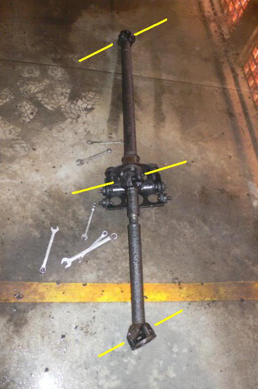 * This diagram is purely to show the rear shaft section flange angles. It is not a Rover P5 facsimile. The centre bearing arrangement is different. 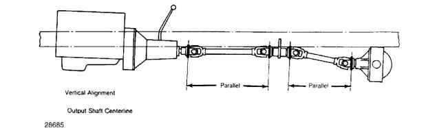 |
|
|
|
Post by lagain on Oct 17, 2023 17:16:58 GMT
If it was OK before the gearbox was taken out the chances are that it is something to do with that.
Have a look on each section for a balance weight and if there isn't one take it to a specialist to have it checked
|
|
|
|
Post by Jens Munk on Oct 18, 2023 7:33:01 GMT
Oh yes, this can be very tedious and unfortunately the factory manual is of no help. If the person taking out the transmission has been unaware, the prop shaft could easily come out of alignment. The transmission mount is shimmed and engine mounts may have been replaced with some of a different height both affecting the inclination angle of the engine/transmission. The prop shaft center bearing assembly is height adjustable and there could be rear spring issues preventing a correct angle of the rear universal joint. Since the engine/transmission combo is installed in the sub-frame separate from the body with the center mount, how is the sub-frame and its rubber mounts.
Obviously the shaft parts themselves must be properly balanced.
I spent a lot of time and effort in getting mine right and ended up having to install 2 deg wedges between the rear springs and axle to get it right. A rebuild of the the partly rotted out sub-frame helped too.
|
|
|
|
Post by Jens Munk on Oct 18, 2023 7:52:34 GMT
The angle or more specific the inclination angle vs horizontal if the engine/transmission and front prop shaft are easy to measure with one of these:
Just google "digital angle gauge" or "digital angle finder", and you will find one in an online store somewhere. The Rover V8 engine valve covers are completely flat and parallel to the crank shaft, so this angle can be measured there. The front prop shaft is mostly a straight tube, so its angle can be measured pretty much anywhere on it although one should be aware of balance patches and paint droplets.
As mentioned below, these angles must be the same.
This may assist. The picture below illustrates the correct phasing of the universal joints. Note: The front section of the driveshaft up to the centre mount should be in a straight line with the main bearings of the crankshaft. If this confuses you, imagine a straight line from the centre of the front harmonic balancer (or pulley) extending straight through the engine and through the centre of the torque convertor or flywheel (as the case maybe). This front section needs to be aligned with the centre line of the crankshaft. The other half or rear section of the driveshaft from the centre mount position should meet the criteria below. The centre mount driveshaft flange angle needs to be parallel to the differential pinion flange. Viewed from above, the driveshaft would be seen as a straight line. Viewed from the side, the driveshaft would be in a straight line with the crankshaft to the centre mount, at which point it would dip down to the differential pinion. Both the flange at the centre yoke (just in front of the splined sliding joint) and the differential pinion flange should be parallel to one another. * Take a look at the alignment of the universal joint yokes carefully and set it up as shown. * This diagram is purely to show the rear shaft section flange angles. It is not a Rover P5 facsimile. The centre bearing arrangement is different. |
|
|
|
Post by enigmas on Oct 18, 2023 13:38:02 GMT
If you want a "Digital Angle Finder", then simply download this app onto your mobile phone. 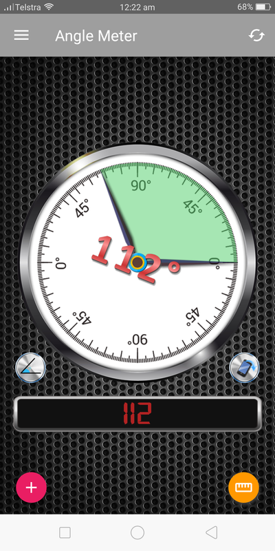 |
|
thor64
Rover Fanatic

Posts: 138
|
Post by thor64 on Oct 18, 2023 17:38:07 GMT
This thread will be of interest to me as I am contemplating re bushing and refurbishing the centre mount of my prop shafts.
I too, having taken my engine and gear box out, had the auto box rebuilt. I took the precaution to mark the position of the drive to the universal joint so it would go back as was. Months later I replaced the rear diff seal and again marked the position of all so they would go back as was. I do wish I had just taken the whole prop shaft assembly out as one then, as the manual says, as I am going to have to remove it all again. This is to replace the centre mount bushes and bearing as these need work. While the whole prop shaft assembly is out I will be looking for damage to the prop shafts. There is a tendency for old unrestored wrecks to be moved around by using fork lifts with the possibility of bending under body parts.
The information here is being very useful.
|
|
|
|
Post by djm16 on Nov 5, 2023 11:52:19 GMT
I am late ti this thread. But there is an additional variable that is perhaps even more important, and that is that the gearbox output flange and the diff input flange should also be parallel. It will vary with worn / bent rear springs, but can be corrected by fitting wedges under the shackle bolts.
|
|


