|
|
Post by David on Jun 20, 2013 8:07:37 GMT
Posted on behalf of Ken Rickaby
Hi, I have just removed the prop shaft on my P5B, replaced all three
UJ's and the four rubbers and two large ones on the centre bearing
carrier. I marked up the prop yoke carriers at gearbox end, short prop/
diff end and short prop to front prop. When replacing the UJ's the fit
to the front prop yoke was perfect with good fitting circlips, the short
prop both yokes two cups of the UJ fitted well with circlips but when
fitting the other two circlips the cups refused to pass the circlip
grove, on comparing with the old UJ's the cups of the new were found to
be 3cm longer. After over coming the problem I refitted the whole
assembly ( don't recommend fitting the centre carrier too many times)
and road tested. On reaching 28mph I had a slight vibration which
increased quite bad as the speed reached 35mph. I returned to the garage
and jacked the car back up thinking that I had not married the marks up
on the yokes which I had. I then started to doubt what I had done so it
then became a game of elimination.
First I disconnected the rear prop from the front (removing the centre carrier again)
and turned it one half turn and reassembled and road tested, vibration still their.
I then decided to remove the short prop from the diff pull out from the
spline end, one half turn and reassemble, this was suggested as I may
assembled the splined yoke half a turm to the yoke on the prop after
fitting the new UJ. Road tested vibration still there.
I'm wondering if anyone can guide me from here or suggest where or what I
can look at or try, much appreciate any comments.
Thank you
|
|
|
|
Post by eightofthem (Andy) on Jun 20, 2013 8:55:05 GMT
What is the condition of the rear gearbox mount?
|
|
|
|
Post by eightofthem (Andy) on Jun 20, 2013 8:59:29 GMT
Sorry forgot to ask about the small spring that is attatched to the rear prop bracket, is it still attatched also?
|
|
|
|
Post by johnwp5bcoupe on Jun 20, 2013 10:05:41 GMT
Hi Ken I did reply to your PM  After checking Andy's recommendations and if the problem is still there? How did you overcome the cups being too long? 3mm not 3cm? Are all the UJ's in the same phase? For a P5b the 3lt WS manual diagram is wrong shown as a parallel/parallel and it should be crossed parallel! |
|
|
|
Post by enigmas on Jun 20, 2013 10:25:07 GMT
Ken, I still use the complete Rover tail-shaft assembly from the gearbox to the differential flange on my Mk3 P76 V8 but do run a different diff centre and have made some subtle modifications to how it is held in place at the centre bearing. Vibration can become apparent if you have the shaft out of alignment when 'viewed from above'. From the coupling near the centre bearing it can veer to the left or to the right. Imagine you have x-ray eyes and are viewing the alignment of the shaft from above...birds-eye view. From this view, the 'whole assembly' needs to be straight or virtually straight from the gearbox to the flange on the differential. Otherwise it's like trying to spin-up a bent one piece tail-shaft.
The view of the shaft from the side is quite different. From the centre bearing it should drop down to the differential flange (imagine a slight bend). The adjustment on the 2 rubber mounts and the spring is critical for correct alignment. Are the 2 rubber mounts worn and grooved? Is the spring actually doing anything or is the centre assembly like a big chunk of jelly?
|
|
|
|
Post by djm16 on Jun 20, 2013 13:51:29 GMT
Different UJs from different manufacturers will have different depth cups. It makes no difference to the fit. What does is the thickness of the base of the cup, because it is the base that determines how far from the end of the spider the circlip sits. If you have a cup that will not go past the bottom of a circlip groove, chance are that you have dropped a roller. There is only one way to do this job properly to end up without vibration. You have to start with the right parts. I cannot recommend those bought from our usual main supplier of P4 and P5 parts. Instead you should order direct from Hardy-Spicer at a fraction of the cost. Next, you need to pop mark all the UJ yokes pre-dismantling. On reassembly, of course they go back the same way. Check also before disassembly the the arrows on the sliding part of the centre shaft line up. On re-assembly, it is worth giving the cup holes a clean up with some wet and dry especially the bits outside the circlip. If the cup holes are worn and a cup goes in crooked, the UJ will bind and cause vibration. So it is worth check that the UJ moves freely in 2 directions before sticking on the car. Similarly, clean up the mating surfaces of the yoke back plates (where the four bolts go through to hold the yoke to the gearbox output shaft or the diff). You can also get vibration from a severely worn gearbox output shaft bearing or diff from nose bearing. I doubt that the propshaft geometry has much influence on vibration. They are designed to operate continuously outside of a straight line. If they did not, the UJs would wear out quicker. The propshaft also has to cope with a wide rang eof geometries depending on how many bags of cement you have in the boot, or MsIL in the back.  |
|
|
|
Post by johnwp5bcoupe on Jun 20, 2013 15:12:48 GMT
What confused me is the 3mm and how it was got over? Roller on it side?? I know when I had my prop balanced the new joints needed different circlips and the company carried a selection which were slightly off set or thicker to compensate for suppliers and mine were genuine Hardy Spicer of today's manufacture not to say the same or as good as 40+ years ago  give the joint a good clout with a copper hammer if they are too stiff or too sloppy recheck for float or lack of they should have a slight resistance if new not stiff. I had 4 visits to the experts to have my prop balanced they insisted making the centre flange parallel/parallel would make no difference to the vibration I was having they said  after all the waiting and travelling not to mention the fitting on and off! I insisted it was made back to crossed/parallel and strangely all was well at last!! If you look at the early P5 it had tapered shims in the axle clamps to raise the diff nose and the shaft was parallel/parallel "interesting"
The only thing you need to pop mark is the centre flange if changing the Metric bearing and rear sliding joint, no point in worrying about the GB end or Diff end just make sure they are all in the same "Phase" and as djm16 says the arrow on the rear shaft is in the correct position as taken off not necessarily the mark on the shaft so mark this these were sometimes moved to correct vibration or may be a combination of two shafts? who knows? All these joint have a optimum working angle at least 1 degree and a maximum of 3 degrees and having spent a bit of time working on my project the Rover P5b set up is not the best and works outside these upper limits on the 2 rear shaft UJ's from new, ideally the UJ angle at the GB should be the same angle as the one on the diff if you carry 6 people in the back and a sack of coal it is better  but it works! The centre bearing height makes a difference and the setting will vary depending on how low the nose of the diff is? |
|
|
|
Post by Steve P5b on Jun 20, 2013 15:16:29 GMT
|
|
|
|
Post by johnwp5bcoupe on Jun 21, 2013 7:20:02 GMT
nice one Steve |
|
|
|
Post by djm16 on Jun 21, 2013 12:43:33 GMT
I am happy to show my ignorance, but what does this mean?
|
|
|
|
Post by johnwp5bcoupe on Jun 21, 2013 13:38:20 GMT
That's not ignorance djm16 Crossed Parallel is where all the driven yokes are in line and Parallel Parallel is where one is 90 degrees out as per the rover P5 manual, this was more difficult in my case as the company welded the splines on the front shaft 90 degrees out and because of the spline count you couldn't put it right Crossed Parallel (picture from Miguel) 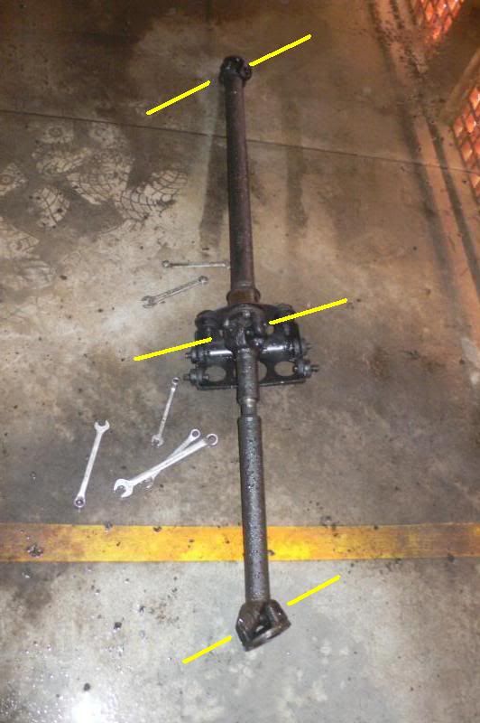 |
|
|
|
Post by enigmas on Jun 22, 2013 1:02:13 GMT
Ken, if you marked all the universal yokes before dissasembly they all should be correct. I tend to think from re-reading the threads that the centre bearing flange and the diff flange are at differing angles causing an out of phase vibration. Both faces of the flange need to be parallel to one another. Think of the first section of the shaft as an extension of the gearbox flange. All the variations in angles take place between the flange at the centre bearing and the differential flange. Trying to ameliorate this vibration by adjusting the rear section of the shaft 1 spline at a time will just confuse and aggrevate the problem. Under engine torque the differential pinion flange will want to climb so take this into account.
|
|
Deleted
Deleted Member
Posts: 0
|
Post by Deleted on Jun 22, 2013 7:51:00 GMT
I replaced the engine and box in my transit,the prop shaft had to be made from the front end of one model with the rear of another and needed shortening.It is a two piece one.
I had it balanced twice but still found a vibration at 30mph that went at 35. Eventually I resorted to the trial and error and jubilee clip trick. After an afternoon spent grovelling underneath I ended up with a smooth ride.
(Well as smooth as a forty year old transit can be that is)
|
|
|
|
Post by johnwp5bcoupe on Jun 22, 2013 9:12:29 GMT
I think it would need a big old circlip Kev if he has problems at 25mph I would think it is there from take off?
|
|
|
|
Post by enigmas on Jun 22, 2013 11:46:00 GMT
If you have the opportunity Ken organise an inspection of your car on a hoist (drive on type) and check out the alignment of all the tail shaft elements
|
|


 give the joint a good clout with a copper hammer if they are too stiff or too sloppy recheck for float or lack of they should have a slight resistance if new not stiff.
 after all the waiting and travelling not to mention the fitting on and off! I insisted it was made back to crossed/parallel and strangely all was well at last!!
 but it works!


