|
|
Post by enigmas on Jun 1, 2017 10:25:16 GMT
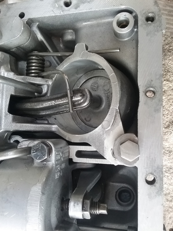
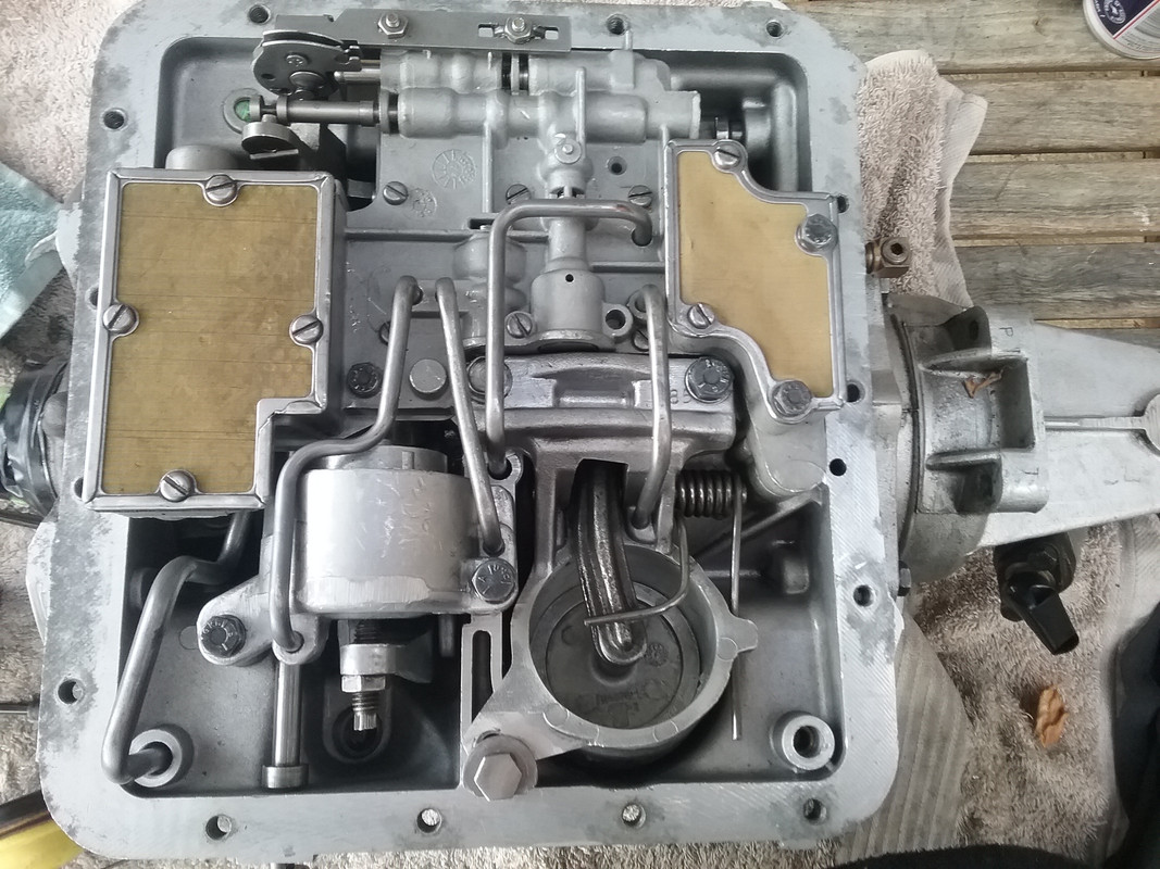
I returned from a road trip with a car club last weekend, ostensibly to go to the classic/historic bike & car races at Winton in Benalla (rural Victoria), but there are wineries, gineries, restaurants and countless antique shops to take your interest as well. My P5 coupe drove there and back seemingly without issue. The following day I noticed a small coolant leak coming from the heater tap...thought I'd fixed it, but obviously not. The small diaphram seal inside the unit was past it's prime...so I ordered a complete new heater valve from the UK, c/o ebay. Then I went to start the car...lots of cranking. No go! Most unusual. The car is full time LPG and I eventually noticed that the LPG switch wasn't lit. No glow from the LED indicator. So I fiddled about under the parcel shelf where the LPG module is fitted. All of a sudden, the LED lights up. So there's a loose wire...the power feed under there. Something else to attend to! Now I think I want to move the car back and to one side in our roofed driveway. This will allow me more room to work and contort myself between the open DS door and seat. I need to get my head under the parcel tray to access the module and wiring. Awkward but manageable. I start the car, move it back a few metres then forward again, then notice that the car's rolling backwards in 'Drive'! All forms of propulsion in any direction has disappeared. This has not been a welcome trifecta! To cut a long story short...I did the usual checks and then decided to remove the transmission pan and valve body to investigate. Once the pan was off the cause of the problem was clear. What eludes me is how it occurred? Here are 2 images...see if you can find the cause of the problem. (The pictures are a bit dark, but I was laying on my back under the car) After you've discovered the problem...and if you have any ideas as to how/why it occurred, I'd be pleased to take note. 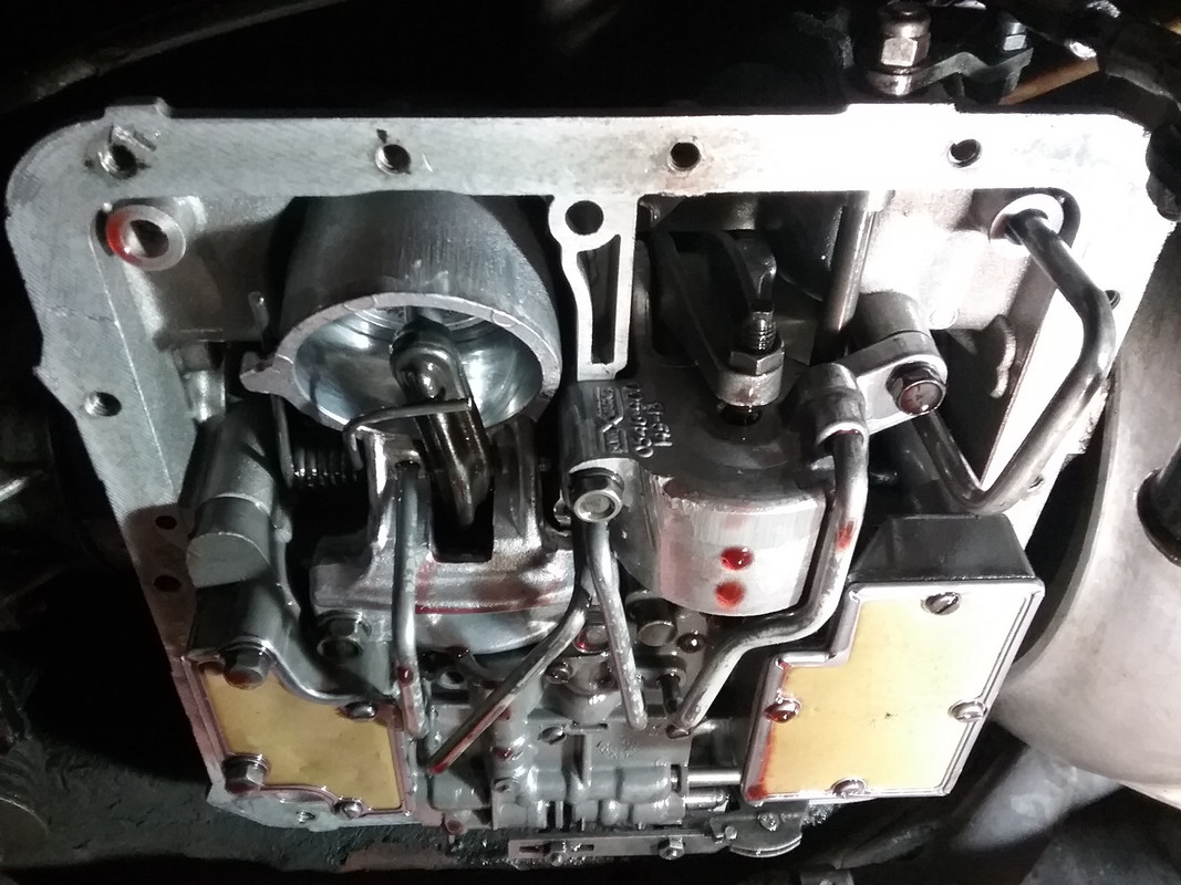 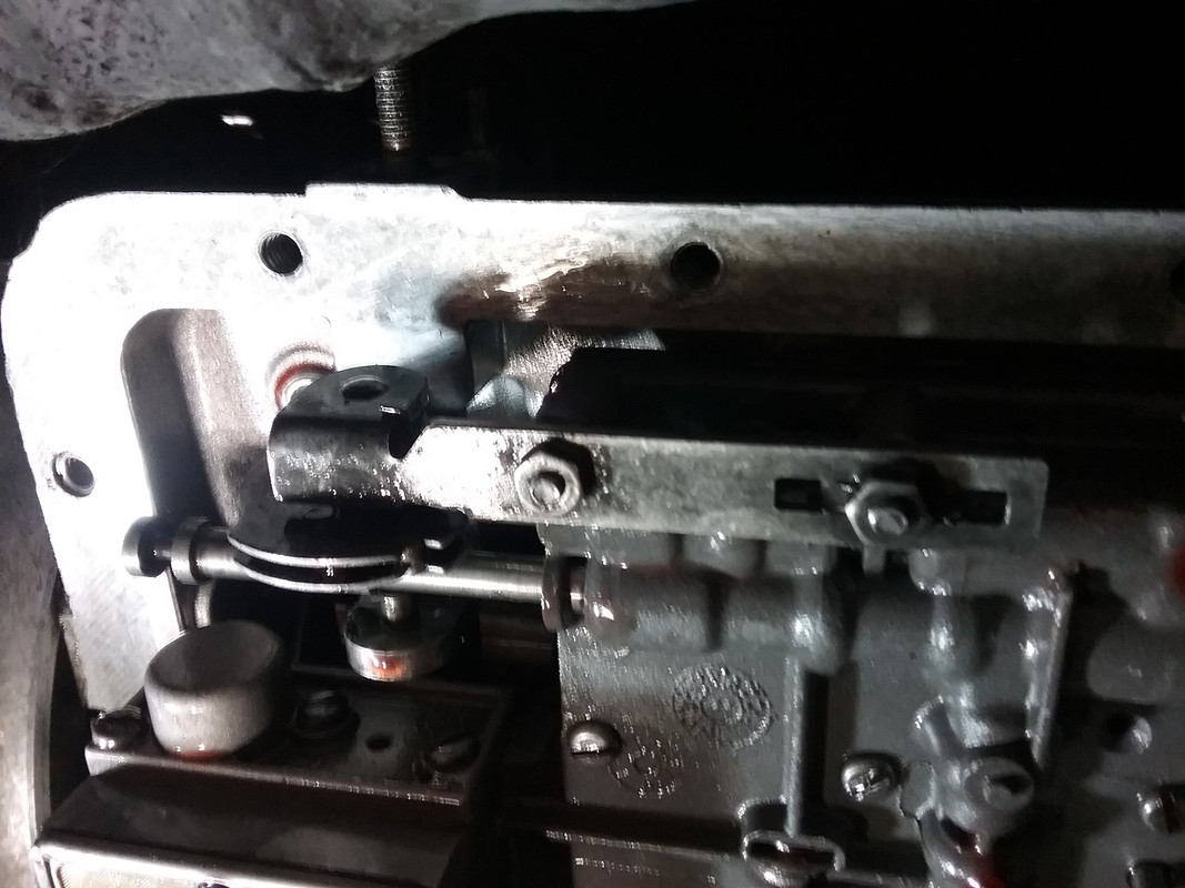 |
|
|
|
Post by barryr on Jun 1, 2017 10:33:40 GMT
Is the kick down cable missing? - has someone pinched it  !! |
|
|
|
Post by enigmas on Jun 1, 2017 10:38:22 GMT
Very warm Barry. You're almost there. Consider, even if the cable was disconnected (and it's not) the car would still drive. Enlarge the photo you're looking at as much as possible.  |
|
|
|
Post by eightofthem (Andy) on Jun 1, 2017 12:19:47 GMT
The manual select rod has disengaged from the manual selector mechanism selector pin.
The valve body may have been loose, or the actual selector mechanism in the case may be missing it's circlip allowing it to move inwards a little bit.
EDIT.
I notice yours has the cross shaft selector, so you might need to add some shims to the inner side ( in front of the roll pin, or split pin ) to take up any side to side free play.
|
|
|
|
Post by enigmas on Jun 1, 2017 23:33:28 GMT
Very observant Andy...that's exactly what has occurred. Strangely enough it happened in the driveway.
When I first looked under there the 'manual control valve' was floating free...totally slipped out of engagement with the gear selector pawl. Hence no power flow to any drive circuit.
Interesting to note that the gear selector cross shaft end play was one of the first things I considered and then checked with a substantial lever. There's negligible end/sideplay! What is noticeable is that the pawl that engages the manual control valve is at the lower point of its arced travel when engaging PARK. (If you're not familiar with this think of the arc of a 'semi circle' and then consider the points at each extreme end of the arc). These are the low points of the pawl's movement. At the park end, the pawl is at minimal engagement with the slot on the manual control valve.
I think what occurred is that the selector mechanism within the car (the selector mechanism utilized is a MK3 column shift) coupled to a 123DNRP valve body...modified for an extra position...has moved (at the gear selector/lever end) too far into the park position and disengaged itself.
The linkage system has been in place for over 20yrs of regular use before the car was put on club plates...so I can't really complain.
As this gearbox has threads on both ends of the cross shaft I can add a restraining washer and nyloc nut to the other end to minimize any inherent side play and of course check and adjust the external selector rods.
|
|
|
|
Post by enigmas on Jun 2, 2017 6:29:33 GMT
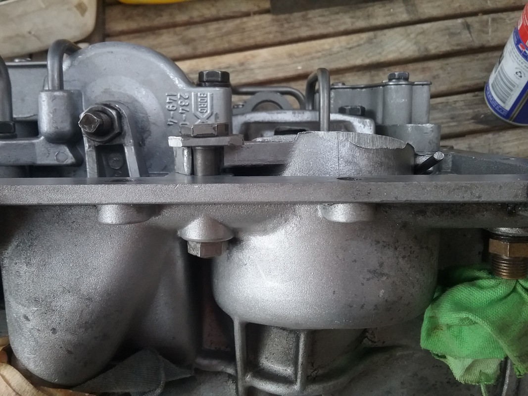
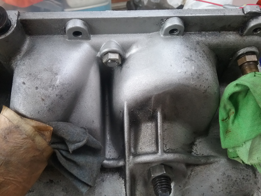
Postscript: I thought I was progressing well until I decided to refit the valve body. Once it was in place I noticed a gap on the seating face of one of the rear servo bolts. Looked like it may have been a bit loose but it wasn't. So I decided to remove it. Now the primary cause of the lack of gear selection was obvious. The picture says it all. 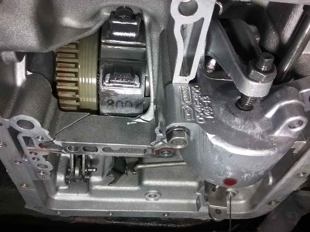 Interestingly the rear servos on all BW35s/40s are the same. Only with the BW51 was the rear servo given an extra locating lug at the far end of the servo to limit/stop any propensity for the servo to lever up and down on its 2 mounts when being applied. All the other internals look to be in excellent shape as far as I can currently see. The rear clutch drum is still in remarkable condition. Hmm...most of you know what comes next!  |
|
|
|
Post by vincentacres on Jun 2, 2017 7:25:55 GMT
You fit a ZF4HP22 👍🏻
|
|
|
|
Post by enigmas on Jun 2, 2017 9:51:47 GMT
Almost correct Owen, I've actually got 2 ZFs in my shed. One from a Range Rover and the other from a Jaguar sedan (the version with the rectangular headlights...I forget the model for the moment) The Jag has the short tailcone but not a mechanical speedo drive and the Rover has a built in inhibitor switch for starting whilst the Jag has a weird electronic thing built into the floor change mechanism. Unfortunately I'm not ready for that yet as it is to be coupled to a fresh P76 engine I'm building (just got the heads back from my friend Basil at Headworks...after 2 1/2 years). So there's some work and modifications required yet. What I do have though, is another Rover MK3 BW35 with BW40 internals that I built about 20 years ago as a spare sitting in a cupboard. I'll strip it down to check and reseal it after all this time, then pull the whole engine and current gearbox combo out as a unit and give everything under the bonnet a freshen up and clean. It's been over 24 years since I had the combo out last...so this gives me the opportunity (ho ho  ) To tidy and repair wiring, etc, etc. Fortunately, I don't need to use it as a daily driver anymore as it's on the CPS, so I can give it some TLC.  PS. I'm definitely going to do something about the rear servo mount though. Most likely modify it for a third mount at the far side. |
|
|
|
Post by vincentacres on Jun 2, 2017 23:50:27 GMT
Sounds like a plan Vince!
Remember when you do get to the ZF though the Range Rover one if you have all of the torque converter assembly and bell housing etc will bolt straight on. The inhibitor switch wires are a simple splice and the Jaguar prop shaft connector will bolt straight to the Rover one
I think the Range Rover tail assembly for want of a better word is fine from memory. I would have to check mine but I think that's what I used. Peter in NL I think used a different one with a different mount approach to me.
The lack of speedometer drive is a pain though 😩
|
|
|
|
Post by enigmas on Jun 3, 2017 4:01:26 GMT
Hi Owen, thanks for that info. Unfortunately the Range Rover gearbox connects to a transfer case so the output shaft needs to be swapped with both the tailcone and the output shaft from the Jag unit...or I can use the complete Jag unit and fit the inhibitor switch from the Rover box to the Jag ZF. I still have to get hold of a drive plate and spacer for the torque convertor. I don't think the Rover V8 and the P76 crankshaft flanges are the same (?) so that's another issue.
The Jag ZF valve body looks to be more complex than the Rover...perhaps more responsive as it's not meant for 4 wheel driving escapades. As you can see nothing is straight forward.
|
|
|
|
Post by petervdvelde on Jun 3, 2017 6:20:26 GMT
i used LDV box with the mechanical speedo which is handy although the speedo shows a approx 30% lower speed then you actually drive so it should be modified which i haven't done yet. I read you can use a Dakota digital speedo set up for the Jaguar box up but this seems to be rather expensive. This comes with a small motor.
I used a combination of the LDV mounts and the P5B mounts and the propshaft has to be shortened for the LDV box.
Peter
|
|
|
|
Post by vincentacres on Jun 3, 2017 8:41:59 GMT
Yes the RR box has the transfer case setup etc. my box originally came out of a Volvo and I had it re-built with upgrades as per some of those described on the Ashcroft Transmissions website and the internals swapped into a spare case - which maybe was a Jaguar one - will hBe to consult old notes to check.
The length is the same as the BW35 so no shortening of the prop shaft necessary and I had a choice of 3 tailpiece setups to play around with to work out how to best fabricate a mount - which I ended up doing with a tuner mount/block from a BMW.
Peter your selector setup is a more elegant solution than mine which was really an interim solution using the existing selector and rods lengthened in various place - workable but not as smooth as befits the old girl!
|
|
|
|
Post by petervdvelde on Jun 3, 2017 9:04:48 GMT
Peter your selector setup is a more elegant solution than mine which was really an interim solution using the existing selector and rods lengthened in various place - workable but not as smooth as befits the old girl![/quote]
It was a fair bit of work to make it but it works so smooth and direct every time so it was worth it
Peter
|
|
|
|
Post by enigmas on Jun 3, 2017 9:21:14 GMT
Given the detail you just outlined Owen what valve body did you use in the end? I have the Jag (XJ40) torque convertor as well from the same car.
The electronic speedo in the Jag is provided with a signal from a transducer reading from the differential pinion flange. A signal from a cruise control transducer (mine is mounted just behind the BW35 gearbox flange on the tailshaft) may also work if the Jaguar internals were transposed to the P5 speedo case.
|
|
|
|
Post by djm16 on Jun 4, 2017 2:05:40 GMT
Is replacing it with a DG box an option?
|
|
|
|
Post by enigmas on Jun 4, 2017 10:14:35 GMT
No...unfortunately that would be a retrograde modification or upgrade. The DG automatic though strong absorbs huge amounts of power and kills performance. The automatic in my coupe is essentially a BW40 in MK3 case. Its probably covered at least 200,000 kms, most likely more in the 20 years that it was my daily driver...so I can't really complain. Apart from the case cracking (cause rear servo flexing on it's mount) the rest of the gearbox could be slotted straight into another case. Fortunately I have another complete BW35 gearbox (with BW40 internals) as a spare and this will be fitted until the ZF is ready. I found something today in my stash of parts. I didn't realize I had one...a BW51 rear servo! It was put aside a long time ago and forgotten! Note the 2 rear servos...one for a BW35/40, the other for a BW51. The 51 servo is identified by its third mount. It will bolt straight into any BW35/40 case but the third mount hole is missing unless it's a 51 case. Unfortunately its not just a matter of drilling a hole as the 51 case is slightly modified at this point. 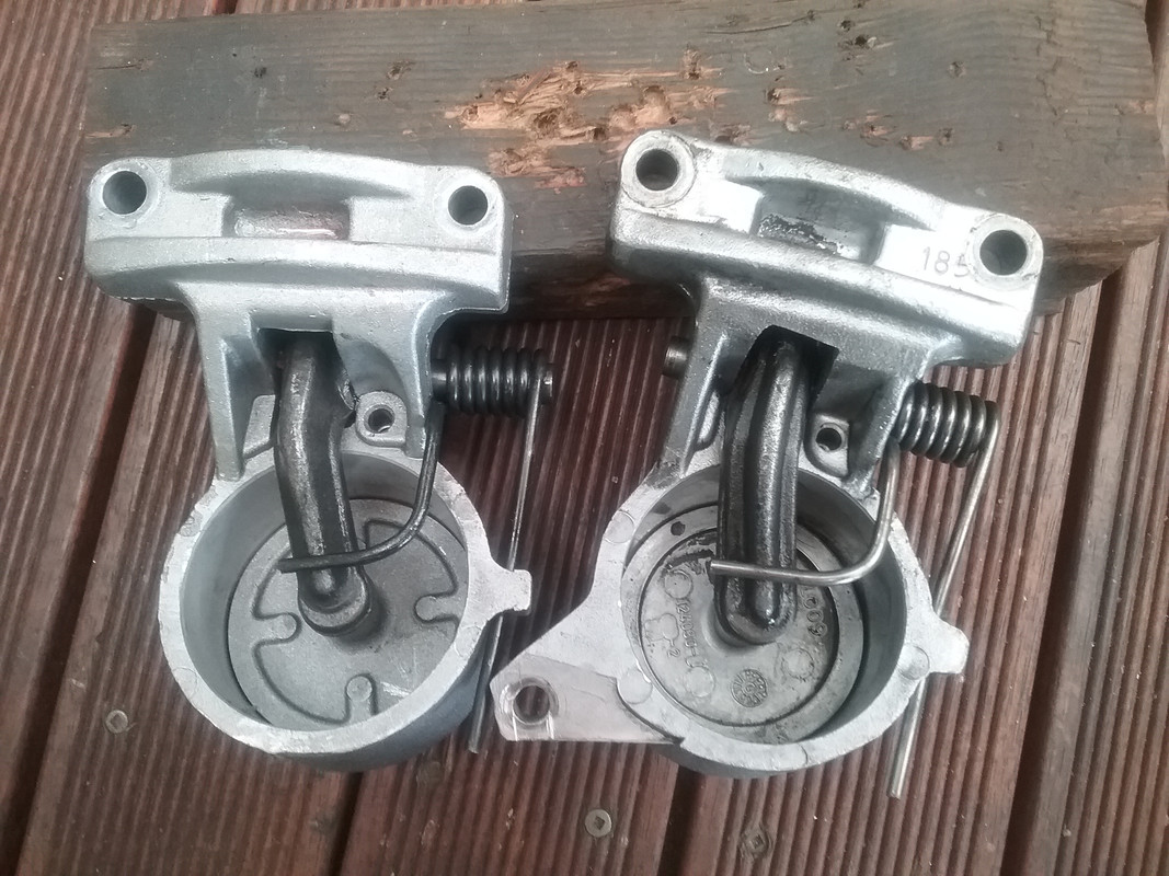 I've decided to adapt this 3 bolt servo to my MK3 case. Consider that the rear servo only comes into operation when selecting Reverse, lock up Low (1st gear with engine braking) or in Park. It actually does nothing in Park apart from clamping the secondary clutch drum...just a design weirdness in the hydraulics. If you ever have the opportunity to look at a BW35 case it's obvious how fragile the rear servo mount is. The casting it attaches to has quite a few cavities/drillings through it and is not very substantial. All the load in either reverse or when in lock up Low flexes this mount. The 3rd mount was added to the BW51 as an upgrade to inhibit any inherent flexing under torque loading. This is how I've adapted it to my BW35 case. 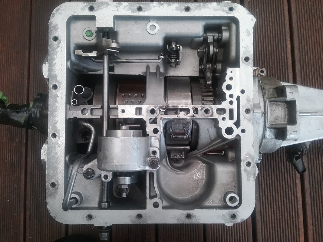 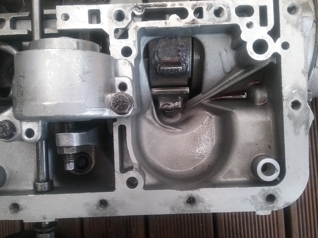 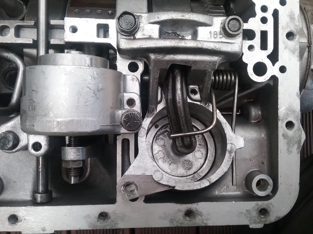 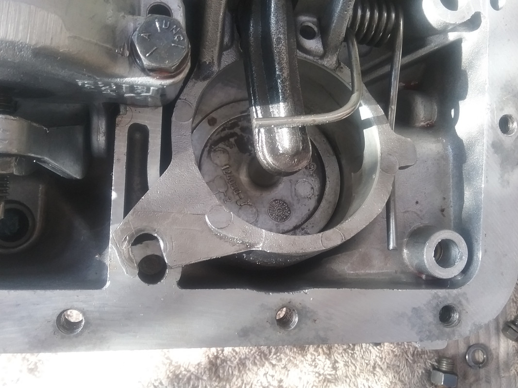 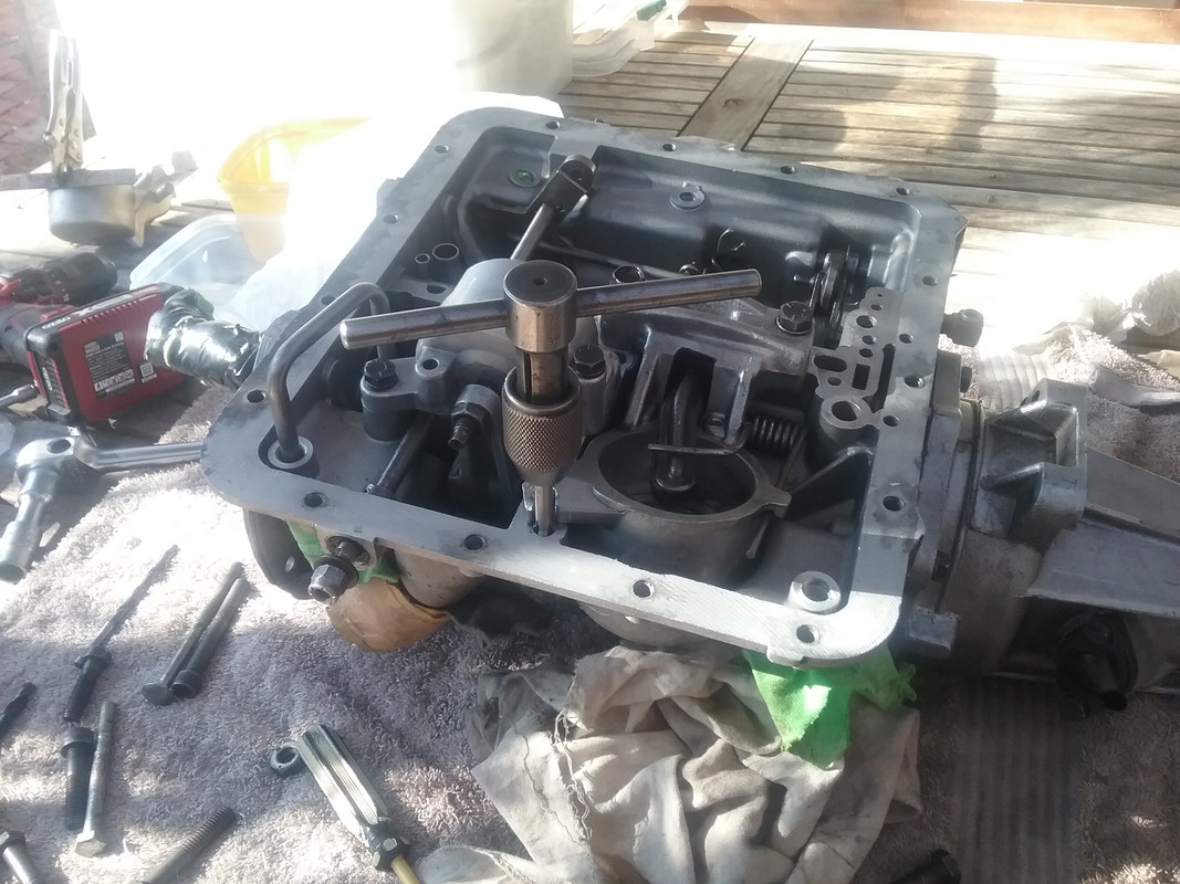 I don't have a photo currently of the bolt I used to secure the third mount (I'll post this tomorrow). Suffice it to say that I found a hi-tensile 3/8" NF conrod bolt that did the job perfectly. Due to the slotted mount I used a 1/8" x 3/4" hardened steel washer (probably a head stud washer) to spread the load. The back edge of the washer had to be trimmed level with the bolt head and the side of the transmission pan relieved so that it would fit back on. Modifying the Transmiission panThe pan required a blister on the side to clear the bolt head. 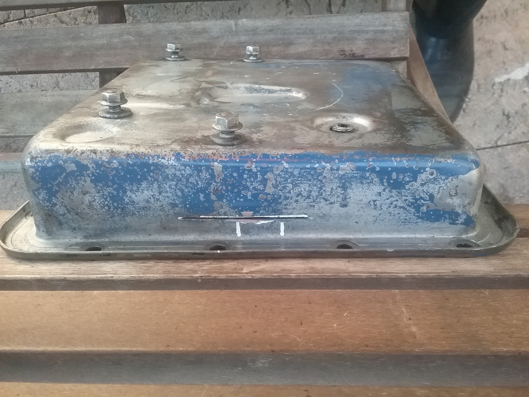 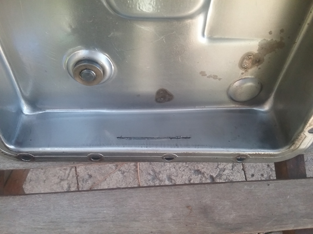 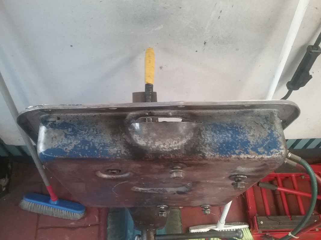 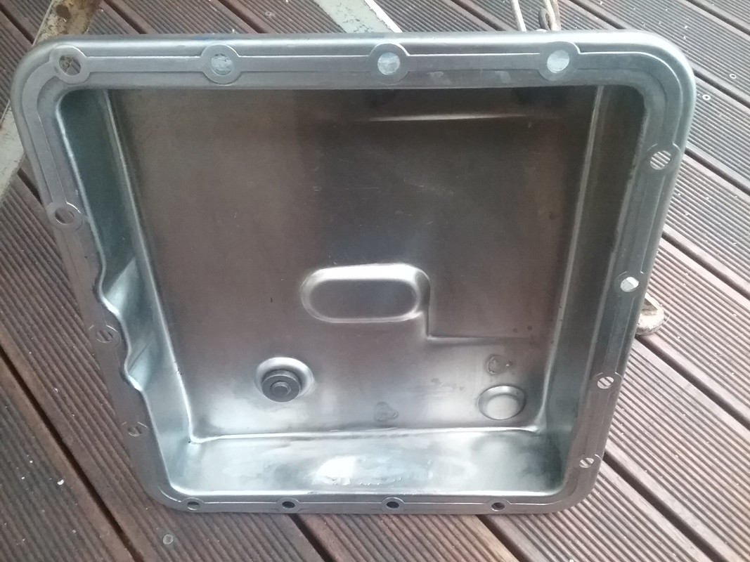 |
|
|
|
Post by djm16 on Jun 5, 2017 0:25:37 GMT
Looking at what you are doing with your box makes me proud to live in Australia! (PR) Were you going weld the reverse servo to fill in around the 3rd locating lug? I won't argue with you over the DG since my suggestion was TIC. Mine is a DG so I am bound to be prejudiced. Yes the torque converter does lose a fair amount of power in 1st and 2nd, but 3rd locks out the torque converter and enables better petrol consumption than a P4 110 and nearly as good as my P4 90 at 23-24mpg on a long run. |
|
|
|
Post by enigmas on Jun 5, 2017 1:08:36 GMT
(DJM16) There really wouldn't be any benefit in welding the hole closed as I'd still need to slot the third mount hole on the servo to reach the hole in the MK3 casing. I'll post this work tomorrow. I also have another valve body (modified to incorporate the rear pump of the MK3 BW35 but incorporating the late model BW40 & BW51 1 - 2 shift valve that allows a light throttle change back into 1st gear...most noticeable when rounding a corner at slow speeds. It's not a kick down action.) On a heavy vehicle like a P5 this all helps to motivate the car and generally feels more lively and responsive to throttle actions. |
|
|
|
Post by enigmas on Jun 5, 2017 10:23:40 GMT
Mounting bolt and hardened washer (to secure the third mount of the servo) Note a section of the washer has been sliced off...this is so that the transmission pan will still fit properly. 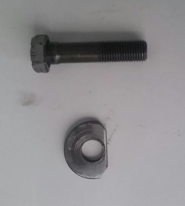 This image shows the 3rd mount held down using the above bolt and thick washer. Unfortunately it's poor quality! 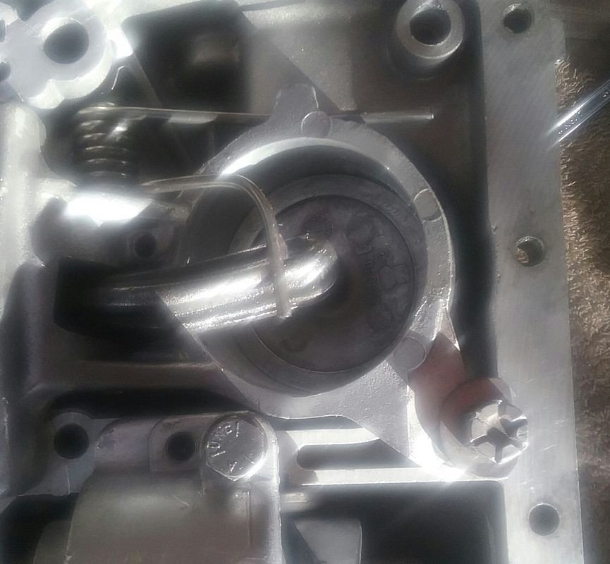 Torn rear servo seals. This is not uncommon and tends to occur if the rear adjustment is neglected. The piston has to move further to take up slack...it cocks-over and tears a piece out of the seal. The third piston to the right has an intact seal. 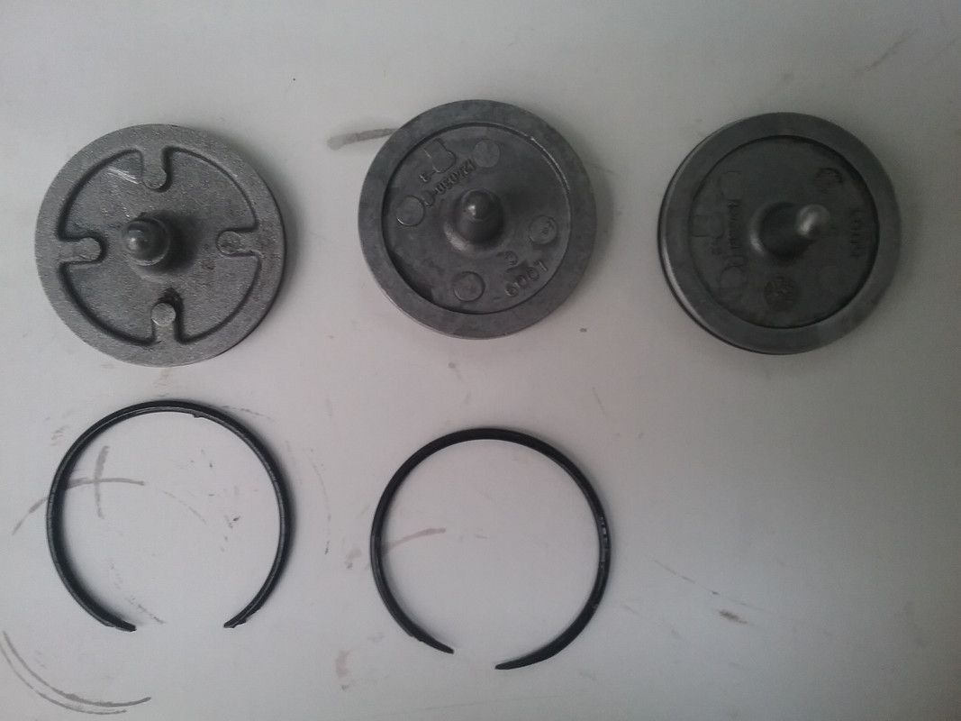 |
|
|
|
Post by enigmas on Jun 6, 2017 8:36:57 GMT
|
|
|
|
Post by enigmas on Jun 8, 2017 2:48:42 GMT
Here are the final images of the hybrid BW35/40/51 transmission for my MK3 coupe. It's now ready to fit after I pull the engine gearbox combo out of the car. 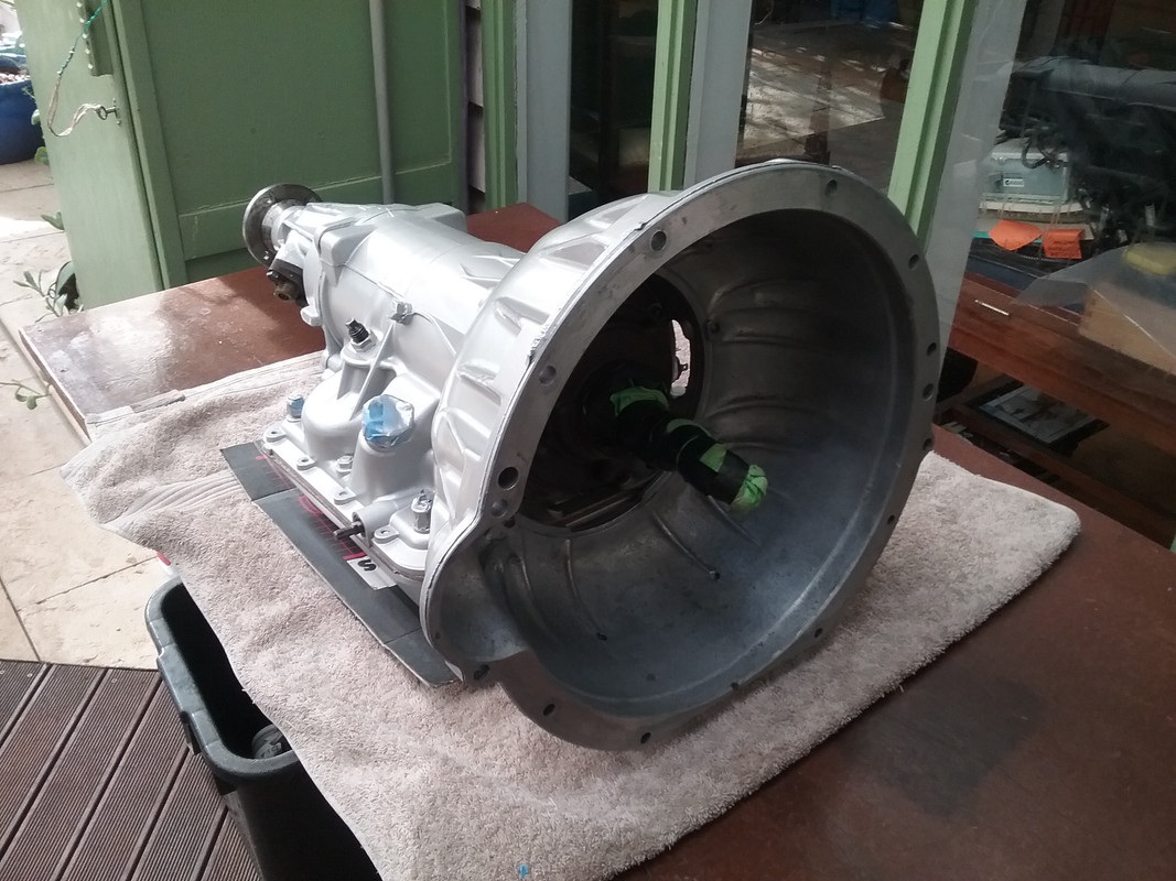 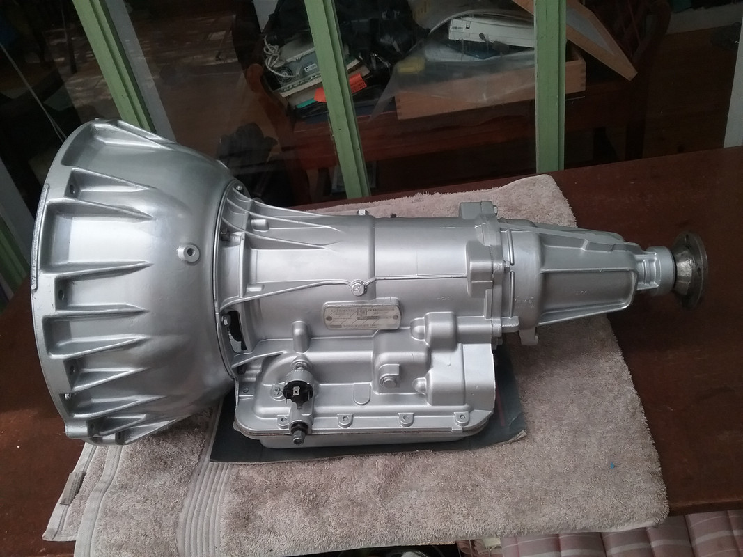 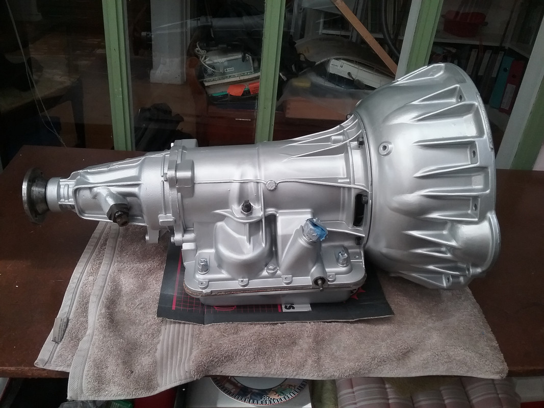 Note NoteThe gearbox is a hybrid due to the following changes. Complete BW40 gear train, heavy duty clutches & bands (Source XF Ford Falcon) in a MK3 case. Largest input shaft and torque convertor (XF) from the 3 versions of each available. (The P5 MK3 runs the smallest of the input shafts and convertors. The stator support is often found with stripped splines on this version) BW51 one way clutch fitted. This has more individual sprags than the 35/40 versions. Composite BW40 XF & P5 Mk3 valve body to incorporate the rear pump, more throttle responsive shift valves (from 3 - 2 & 2 - 1) and the GTS selector pattern (PRND21) The primary valve spring in the XF Valve body produces the highest system pressure. (See photo below comparing the various spring lengths) BW51 3 mount rear servo fitted. BW40 front servo (largest in diameter...for maximum clamping) BW40 transmission pan. (Required to clear the larger front servo. The MK3 rear pump is also still incorporated. 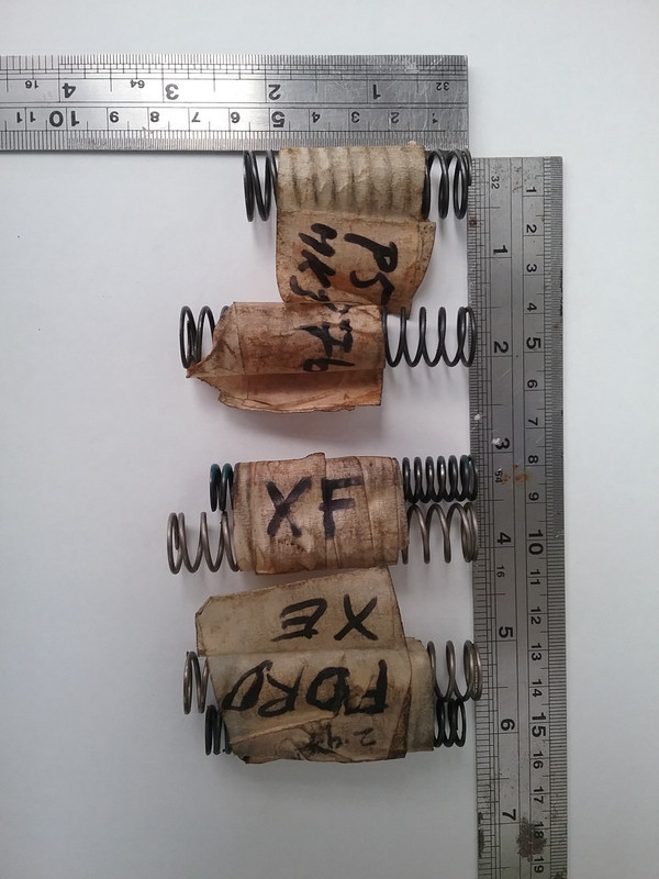 That's all I can recall for the moment. |
|
|
|
Post by harvey on Jun 8, 2017 15:19:20 GMT
BW40 front servo (largest in diameter...for maximum clamping) The earlier pictures showing the cross shaft masde me wonder about that. I rebuilt an MGB BW35 (that has the cross shaft, as does the Rover 2000/2200 P6) and the idea was that as the MGB was to be converted to V8, all the internals were to be upgraded to suit, and there was no way that the largest front servo (the V8 one) would fit, it fouled on the cross shaft. |
|
|
|
Post by enigmas on Jun 8, 2017 22:51:02 GMT
BW40 front servo (largest in diameter...for maximum clamping) The earlier pictures showing the cross shaft masde me wonder about that. I rebuilt an MGB BW35 (that has the cross shaft, as does the Rover 2000/2200 P6) and the idea was that as the MGB was to be converted to V8, all the internals were to be upgraded to suit, and there was no way that the largest front servo (the V8 one) would fit, it fouled on the cross shaft. Harvey with regard to the front servo, I use the largest available in Oz for the BW35. It's taken from an XF Ford Falcon (BW40) and can also be found fitted to later subsequent Ford models. What you may be confused with, are the transmission pans on the English BW35s (MK3s & P5Bs that I'm familiar with) that are not deep enough to clear the top of the front servo and require either some judicious panel beating or a deeper trans sump from a late model Aussie Ford Falcon. Even so, there are a couple versions of oil feed pipes to fit the largest servo...one having a larger feed hole to the servo (BW51 version). If using the feed pipe version with same sized pipe ends (and matching servo) some gentle tweaking of the pipe is required to fit the pan. Clearances are very tight. Interestingly, even the P76 pan is not suitable. None of this tech/mod stuff is sacrosanct to me. It's purely a matter of solving a current technical problem to suit my purposes with the available technology. This is my experience with the range of BW35s/40s/51s available to me in OZ. As for the cross shafts...all the boxes (35/40/51) I've seen have them in exactly the same location...if they weren't in the same location, none of the various valve bodies (up to the last versions BW51) would fit or function as the selector pawl wouldn't engage the end of the manual valve! If you have one available provide me with the external diameter measurement of front servo you're referring to and I'll verify this with the servos I've fitted. Here are the front servo sizes that I'm aware of: In order from smallest to largest front servo. P76, RoverP5 MK3, Ford XF (also in BW51) The XF Ford Falcon front servo is 2 7/16" ID & 2 3/4" OD. 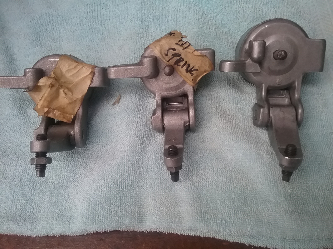 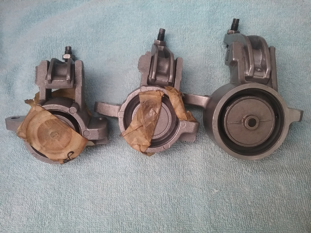 Clearance between the cross shaft and the large Ford servo .030" 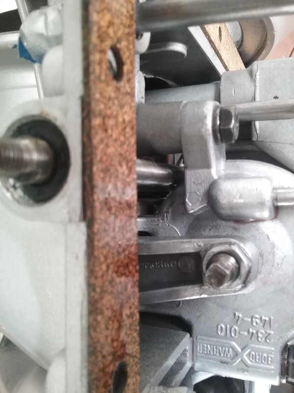 Clearance distance between the trans pan and the servo feed pipe is tight. Note that I've lower the top of the pipe with a persuader.  Note. The cross shaft gear selection pawl still fits into the manual valve without alteration or persuasion 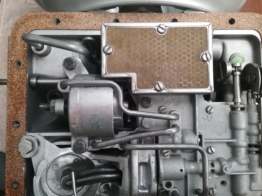 PS. The spring in the servo orifice control valve (SOCV) will also need to be changed (longer version) otherwise a flare will occur using the large front servo. |
|
|
|
Post by enigmas on Nov 25, 2017 5:35:11 GMT
BW35/40 ATF Weeps and LeaksI thought I'd reactivate this post to add some related BW35 and BW40 issues that seem at times to plague any enthusiast that runs a classic car fitted with one of these transmissions. Having recently rebuilt and fitted a spare transmission into my coupe along with a myriad of engine refurbishment tasks generally invites a host of minor adjustments especially after a 5 month period. Adjust or change one component and there's usually a flow on to another related one that's also subtly changed. Murphy's Law I suppose! Well this one relates to transmission leaks/weeps something a BW35 seemingly does as part of its DNA. Fortunately the trans in the main is dry and clean as I replaced all the seals. The first pan gasket fitted was a failure as it weeped ATF from day one. Interestingly this was mainly due to deformations on the sealing surfaces...especially where the pan bolts pass through. I managed to cure this by flat filing the surfaces until they were level as verified by a steel rule. This can be seen on the photos below illustrated by light file marks across the flange surfaces. All the holes were sitting slightly proud prior to the levelling...which took about 3/4 of an hour. After this I coated the pan sealing surface with Blue Hylomar, positioned the gasket, applied a light smear of vaseline to the case side of the gasket, then offered it up to the transmission. This seems to have effected a leak free joint at the pan to case surface. So that's a win. 😊 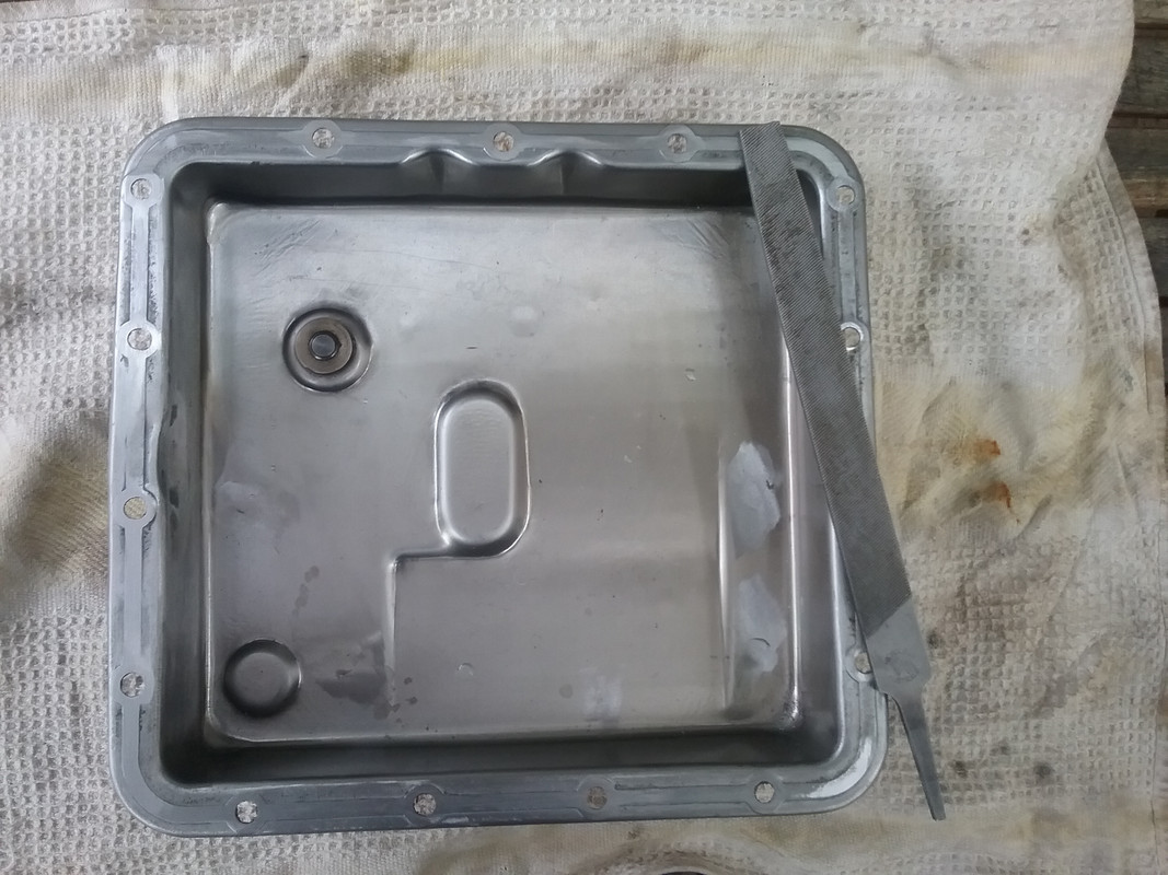 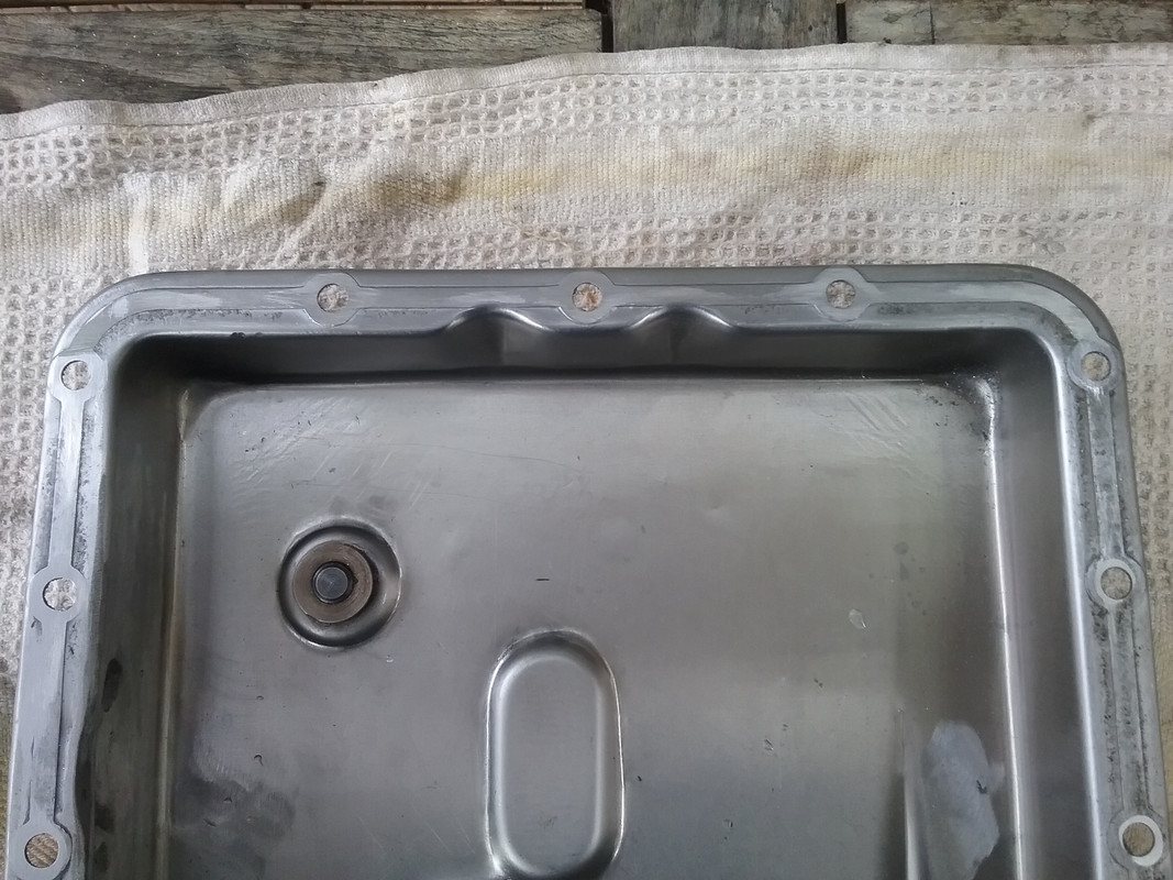 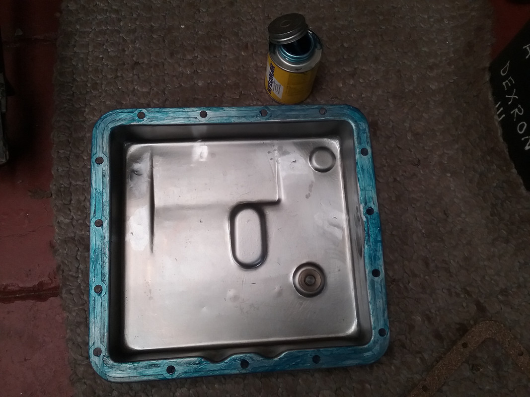 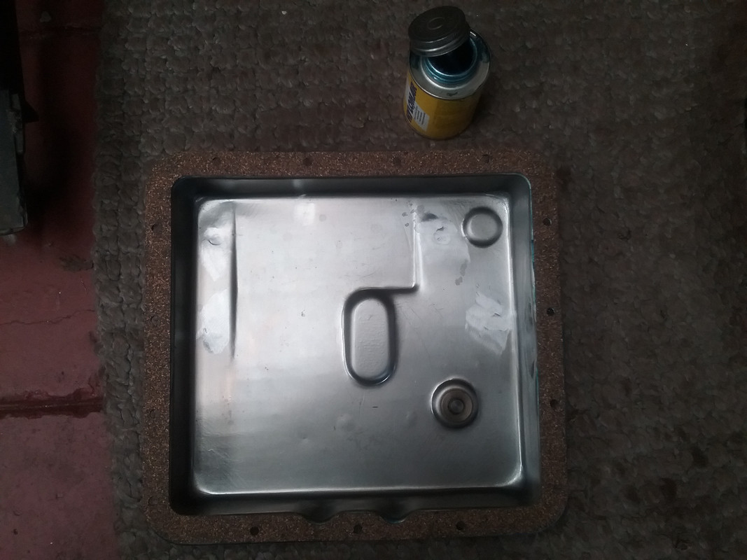 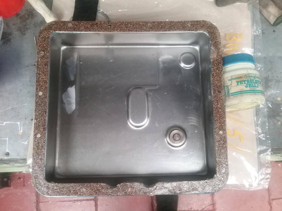 ATF FLUID LEVEL BW35/40/51 transmissions ATF FLUID LEVEL BW35/40/51 transmissions Note: The picture below illustrates the correct level of the transmission fluid (in relation to the dip stick) when the system is at the correct 'running' temperature. The fluid should be in the GREEN zone. With the trans warmed and running, the ATF sits justs below the parting line of the sump and the transmission flange face for the pan. 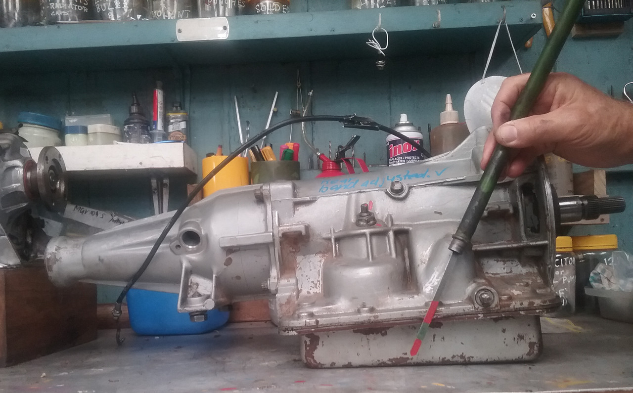 Comments welcome.
|
|
|
|
Post by Warwick on Nov 25, 2017 7:47:56 GMT
Makes perfect sense to me Vince.
I see 3 options.
1. Probably your first choice, based on past experience. Cut the bottom out of the pan and fabricate a sheet-metal pan extension and weld it on.
2. Graft in a smaller (in area) but deeper pan extension onto the bottom that provides the small volume increase that you need so that the level drops by the same amount.
3. Fabricate an rectangular aluminium spacer to lower the existing pan by the required amount. It would be made from aluminium bar and welded at the corners. Its vertical thickness would equal the required depth increase. The horizontal width of all sides of the rectangle would be the same as the perimeter surface of the transmission case face where the gasket goes. You would need longer bolts. You would use the appropriate sealant to permanently bond the spacer to the pan, and the normal gasket sealing method at the new transmission mating surface.
|
|


 !!
!!


 ) To tidy and repair wiring, etc, etc.