|
|
Post by djm16 on Mar 7, 2018 7:19:42 GMT
Part 1. The burned exhaust valve.I had been wanting to do something about the exhaust valve guides for the last 4 years. Apart from the oil getting contaminated, I also was getting a cloud of blue smoke on the over-run, although it did take a 35C degree day and coasting downhill in gear down a 1 mile hill to do it. Cold days and short hills? No problem. When I then burned an exhaust valve, I had no choice but to get on with it. 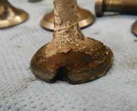 Number 4 exhaust valve has seen better days. If the valve guides are worn sufficiently, the valve can rattle around sideways, causing uneven wear and a fail of the seal between valve and seat. In addition, oil will be sucked through the guide and turn to ash on the seat. This I believe was the main contributor. There was plenty of ash on seats and valve heads. Information in the manual is a little contradictory, but together with numbers gleaned from the internet, I gather that a valve stem to guide clearance of 0.8 to 2 thou is about right, with possibly more clearance towards the valve head. Whether the greater clearance at the head end is by design or the result of wear, Rover do not clarify. Mine had bell-mouthed to something like 6 thou thou clearance as checked by split ball gauge post removal. The next factor is the width of the sealing surface between valve head and seat. I had done a multi-angle job on the seats 33k ago using a stone set as I had the engine out and stripped. Even so, I may well have got the seats a little wide. Lastly, the exhaust tappet clearance will become critical if the rest of the exhaust valve and guide is getting a little dodgy. The trite explanation for too little tappet clearance causing a burned valve is that the valve has less time in contact with the seat and so less time to cool. Hmm. I don't think so. The real reason is that with the correct tappet clearance the valve head clicks smartly back on the seat, dislodging minute amounts of carbon and ash which would otherwise allow gas leakage. With small tappet clearances, the valve head settles gently back on the seat bedding down the carbon / ash without dislodging it. Too wide a tappet clearance and the repeated thumping of valve head on seat will create stress fractures in the valve head and eventual disintegration.
|
|
|
|
Post by djm16 on Mar 7, 2018 7:21:13 GMT
Part 2.Doing the guides, tools needed.My first job was to remove all the old worn valve guides and replace with new. I needed a ground-off bolt to knock the guide out, and a threaded rod to draw the new one back in.   Valve guide knocker (driver) and puller.  Here is the driver sitting ready in the drive.
|
|
|
|
Post by djm16 on Mar 7, 2018 7:21:37 GMT
Part 3. Inserting guides. Taking the sharp edge off the fat end of the valve guide to help it seat in the block. The blue thing is a diamond file from Bunnings.  What about the valve stem to guide clearance? I measured all the valve stems with a micrometer, converted to inches, and wrote the result on the stem. As you can see they are all pretty close to 0.342 with the exception of the new stainless steel valve (far right) which was 0.3405. I was not happy about starting out with 2.5 thou stem to guide clearance with the stainless valve, so in the end did not fit it. Instead I fitted a used Landrover valve kindly donated. So what "should" the measurements be? This simple question caused me an outrageous amount of angst. The manuals do not distinguish between OEM spec, acceptable tolerance and wear limits, and are inconsistent . My eventual conclusion was that the nominal guide dia is 0.343". The "as-new" valve stem dia is 0.343 - 1 thou, in other words 0.342. Why the early engine world should have picked on that precise value, who knows. It is not even a rational number, being close to, but not exactly 11/32". The last question about the valve guides to trouble me, and trouble me they did, was whether or not to ream and hone the guides once in-situ. Some replacement guides absolutely are designed to be fitted, reamed to size and then honed to allow adequate oil retention. Those instructions are explicitly stated by their manufacturer. My guides, as supplied by John Wearing are already reamed and honed to final size. So even though I had bought a reamer, after checking with a split-ball gauge I decided against using it. Given that I had carefully pulled the guides into place, lined up with the valve seat, and not just whapped the things with a sled hammer, I was confident that the guides would not be distorted. 
|
|
|
|
Post by djm16 on Mar 7, 2018 7:21:58 GMT
Part 4. Cutting the seats.  Neway cutters. This is a 31/46 degree carbide cutter. There is a built-in 1 degree difference to the standard angles on a valve that ensures a tight seal. You also need a handle to turn the cutter, and pilot to keep the cutter central. The other cutter in the box is the 70 degree throat cutter. I will freely admit that this part of the job, re-cutting the seats, was a complete nightmare! It took a while and a lot of reading around, but I was eventually happy with the goal: to produce a three angle 30/ 45 / 60 (70 - see later) seat, with a mating / sealing ring width of 1.5 mm. The simplest way to achieve this in retrospect would have been with a set of stones. But I really did not fancy having grinding dust getting inside an otherwise reasonable engine. I was doing this job just with the head off, and the engine still in the car. For that reason I opted for cutters. Your usual seat cutters for cast iron heads will just bounce off a hardened seat. You need special carbide cutters. Mine are from Neway. I thought I was ordering a 60 degree cutter for the valve seat throat, but I ended up with a 70 degree cutter instead. Three of the valve seats cut very nicely, and the sequence of 70 followed by 30 and then 45 until the required mating surface of 1.5mm was made took less than 30 mins for each, with relatively little removal of material required. However the other three seats were a complete sausage. With the very worn guides allowing the valve to drift off centre, the seats were no longer concentric with the guide. With stones, and relatively light pressure it would not have been hard to true them up. But these seats have been in the block for 70 years and have suffered around 600 million hits from a valve head. They were just a little work hardened. It took a huge amount of pressure to get the cutters to bite, resulting in an uneven cut even on a relatively concentric seat. This is apparent when I used a trace of valve paste to grind the valve to match the seat. A section of sealing ring remained untouched. Repeated grinding in with fine paste eventually produced a satisfactory seat.
|
|
|
|
Post by djm16 on Mar 7, 2018 7:22:26 GMT
|
|
|
|
Post by djm16 on Mar 7, 2018 7:22:46 GMT
Part 6. Gouging a seat.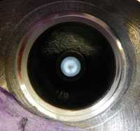 Even with a nicely concentric cut, the pressure needed to get the cutter to bite into the seat and cut led to a degree of gouging, evidenced by the shiny area following the first lapping.   Detail of the shiny bit in the valve seat. With successive grindings with fine paste I eventually got to the RH image. Even to get this far and only have a small gouged area in this seat took several hours and a lot of fiddling, cutting using a small ammount of side pressure to try and compensate for the gouged bit. In the end, I was still unhappy with the seat, not least because I had taken a fair ammount of metal off it. So I knocked it out and replaced it.
|
|
|
|
Post by djm16 on Mar 7, 2018 8:09:17 GMT
Part 7. A seat that was no trouble. In contrast, the first cut on a new insert shows that the insert is nicely concentric on the new valve guide. Moreover, no gouging. Incidentally, the pilot is still in place in the guide. I used an expanding pilot. It is slightly less rigid than the fixed pilots. However, were I working on a guide that has bell-mouthed, the expanding pilot stands more of a chance of keeping the cutter aligned. Blue testing and fine paste grinding with its matching valve also confirmed it was good. (The recommended way to check the sealing surface is with engineers blue. This is a very (VERY) dense dye. It comes in a paste or liquid. The tiniest smear of paste on two mating surfaces will show up any unevenness as a change in the density of the blue.)   It is pretty much impossible to get any kind of measuring tool anywhere near the valve seat to judge the width of the mating surface, so I just held a 1.5mm drill bit close and looked at it through magnifiers.
|
|
|
|
Post by djm16 on Mar 7, 2018 8:09:38 GMT
Part 8. A couple of screw-ups.  Of course there were screw-ups. The first major one was an accident with the 70 degree cutter on number 4. The insert throat was not concentric with the new valve guide, and I did not realise at first just how little pressure a 70 degree cutter needed. The result was that first the cutter jammed, and then juddered while cutting, shattering the valve seat insert. The second screw up was with another seat that was off centre. It took hours of cutting to try and straighten it up. The cutter continually drifted and cut unevenly despite a tight fitting pilot, because of the huge pressure needed to bite into the work hardened seat. By the time I finally was happy with the seat I had cut away more than a millimetre of seat, so decided to replace seat number two as well. The usual advice for removing seats is to hit them with a cold chisel. Too much of a risk of damaging the cast iron block I thought, so I went for option number 2 which is to weld a bead onto the valve seat, which a) gives something to drive against with a drift and b) causes shrinkage of the seat making it easier to remove. With my damaged seats, welding also caused the seat to fall apart so it could then be removed piecemeal. It was easy to clout the seat by shoving a drift through the exhaust port and driving against the weld opposite.  Removing the seat by welding to it. Bits fly out at high velocity, so safety glasses and ducking is a good idea. The Blu-tack is to stop welding spatter getting down the bores.
|
|
|
|
Post by djm16 on Mar 7, 2018 8:09:57 GMT
Part 9.Installing new seats.The advice from the retired Rover specialist was that I would never get a valve seat back in by bashing it. They invariably break. That was certainly true of the first one I tried. I had managed to get hold of two original Rover seats. They are designed to be a whole 7-8 thou larger than the recess in the block that they sit in. Given how hard the seats are, that is a staggering amount of compression. No wonder they are prone to breaking. It was no use cooling the seat. I tried that. Going from +25 C to -20 C must have changed the dia by all of 0.5 thou. The correct way apparently is to knock the valve guide out again (what!) and use a large dia tensile bolt to pull the seat into place. Fortunately there is a second option, and that is to use a special driver consisting of a cut-off valve stem welded into a lump of soft steel. See below:  I was ultra cautious with the (quite expensive) genuine Rover seat ($60 ea from John Wearing, less from elsewhere). A few minutes steady whapping with a wooden mallet (to avoid too sharp a shock to the seat) and it was in place. Relieving the sharp leading edge with a diamond file again helped, as did the trace of moly grease. I had only bought two spare seats, and I had broken one, and needed a second. A long internet search brought up a site for universal valve seats, and one of them was close enough to the right size. Not only that but a local Perth store had them in stock for a small number of dollars. Yay, something going right. In contrast to the Rover seat, they are only about 3 thou larger than the hole they are going into, which I understand is a more usual interference fit. The one I fitted went in with no trouble. It did have a 0 degree top to it though which required a bit of time with the cutters to get to 30 degrees. In comparison to the old seat, the effort required to cut the new seats was minimal. Just a few ounces of pressure on the spring loaded handle and the cutters would bite. It might have been quicker all round to just have knocked out all the old seats and replaced them at the start!   Six new universal seats at less than the price of a new Rover one! Cutting generates a lots of fine swarf than needs regularly vacuuming away, and keeping out of the cylinder bores (hence the masking tape).
|
|
|
|
Post by djm16 on Mar 7, 2018 8:10:16 GMT
Part 10. Conclusion.
1) Neway is absolulely the way to go, especially if all you need is a quick valve seat clean up. Stones are arguably easier if you have the engine stripped and you are straightening up skewed seats, and don't mind having grinding dust everywhere.
2) Don't (as I did) believe "She'll be orlright mate", if the valve guides are worn, you will not be happy! I was not happy for 4 years. Replacing them is not THAT big a deal, especially if the engine is already out. Different considerations apply with guides in an aluminium head, which is beyond the scope here.
3) The engine runs very quietly now (despite setting the exhaust tappet clearance to 14 not 12 thou. There is no more smoke on the over-run. The oil is staying clean.
Now bearing in mind that on re-assembly I also relieved the exhaust ports in the block to match the exhaust manifold, and I adjusted the hole in the economiser to 1mm, so I cannot attribute all the gains to the valve job, BUT I now get 200 miles out of only 37 litres, whereas before it was closer to 40 litres per 200 miles.
|
|
|
|
Post by enigmas on Mar 7, 2018 9:12:30 GMT
Wow...the whole episode (to be continued...) sounds like a nightmare experience to me David! I hope it all works out for you. If you need to, give my friend 'Basil' (Leigh Keir) at Headworks in Carnegie Victoria a call. He's done it all and should be able to clarify the do's and don'ts of your current undertaking. Better to have a chat than something going untoward when you eventually fire up the engine.
As an aside guide clearance can be a critical factor on the exhaust side of an IOE configuration engine as heat is similarly disbursed into the block like a side valve engine. Too little and it may bind and too great reduces heat transference through the guide. It's not purely the seat or the valve dwell time on the seat that accounts for heat transfer. Similarly looser valve clearances (within reason) on the exhausts are safer due to valve dwell time increasing on the seat. A properly ground camshaft will lower the valve onto its seat safely/smoothly by design...but perhaps if it is past its best, the ramp on the camshaft that does this task will be compromised due to age and wear.
|
|
|
|
Post by David on Mar 7, 2018 10:54:50 GMT
If it is Ok with you David I would like to put this in our club magazine 'Take Five'?
|
|
|
|
Post by Phil Nottingham on Mar 7, 2018 19:04:27 GMT
Excellent thread but often especially if neglected the exhaust seats suffer from microcracking and with that kit I would replace the lot
|
|
|
|
Post by djm16 on Mar 7, 2018 23:08:15 GMT
Phil, microcracking. You are right, but I did look very carefully with a bright light and binocular magnifiers.
David, yes feel free to use this for Take Five. It also appears in similar guise in Rover Road (WA Rover club magazine).
Enigmas, thank you as ever for your advice. The engine has now done over 1000 miles, two further headbolt re-torques and two further tappet clearance checks. I did stress about the valves binding in the guides which is why I spent so much time trying to figure out recommended stem to guide clearances. It seems Rover ran them pretty tight from new. I also looked up thermal expansion coefficients for various types of steel and caste iron, and concluded that even at 800 degrees I was pretty safe.
|
|


