|
|
Post by djm16 on Nov 11, 2019 6:46:12 GMT
While we are on the subject of new parts, I realised a couple of years ago that at some point I would need a set of new roller cam followers and so bought 6 from Bearmach (?) I forget who exactly, but they were $ounds 6 each. I thought this quite reasonable as I have seen them elsewhere for several multiples of this price!
6 of course is not enough for a full rebuild, so this morning I ordered another 6. Only after I placed the order did I think to actually open the packet to check for compatibility with my exhaust rockers, and discovered to my surprise that each packet has 4 rollers in it!
So now, instead of having 6 rollers, I realised I had 24 of them. And there is another 6 - 24 of them on the way! Oh well.
|
|
|
|
Post by djm16 on Nov 15, 2019 8:53:13 GMT
I spoke to Clive Cams today. I realise that is not his real name! My goodness what a nice man. He has had a look at my camshaft and reassured me that it will be as good as new when he is done. He commented on the lobes for cylinder 1. "It looks like something hit it". That set me thinking, and then I remembered that I had seen a spiders web crack in the crankcase casting opposite the lobes for cylinder 1, so indeed, something did hit it, but I wonder when? Surely not during initial assembly?  The crack as seen from the outside. Strangely the crack is not visible from the inside.  |
|
|
|
Post by djm16 on Nov 19, 2019 0:18:47 GMT
Musings on cast iron rusting and POR15.
Cast iron first. It rusts like a bandit! I was paranoid about getting rid of every trace of shrapnel and honing dust after the re-bore, so attacked the block with a jet washer again. I had only just been around with some 600 carborundum paper to remove the rust spots that had formed on the cut-aways for the main journals and cam bearing. In the time that it took to wash away the slurry from this, an orange bloom appeared again! Well it can stay there this time, and I have sprayed around with CRC to prevent further rust formation. The real answer is of course to re-assemble the engine, but I am waiting on lots of parts.
POR15. I have written about it before. I am sure that once on, it is an excellent hard-wearing and tough finish. Incidentally the closest colour I could find to a Rover Blue, notwithstanding the known variations depending on supply, was "Chrysler Blue". I suppose I could have bought some plain white to add to it, but there are limits (including doubling the cost). It really bugs me that in the USA you can go into a hardware store and buy a can of POR15 for $20. Here, the same can is at least $70 plus freight.
The adverts showing a VW camper van hand painted in POR15 are a joke! This stuff does not go on well. You have about 5 seconds while the paint behaves reasonably. It goes on smoothly, and flattens out. But 5 seconds is it! If you have not done brushing it by then, you are going to get left with brush marks. If you have to go back over a section 30 seconds later, it is even worse - the top surface has become sticky and thixotropic, and picks up on the brush in lumps, leaving gaps of bare metal.
Why would you want to go back with a brush? Except on the flattest of surfaces, the brushing action raises air bubble in he paint that do not spontaneously pop. A fast skim over the top with a soft brush can pop most of these, but with the risk of dragging the surface off the paint again.
COI: I am pretty experienced at handling a paint brush. I paid for my first year of medical school by painting houses, and have done all my own house decorating since.
I recommend doing the prep that POR advises. I have plenty of the degreaser and rust blaster left over from doing a petrol tank a little while ago, so used those remnants on my block.
|
|
|
|
Post by enigmas on Nov 19, 2019 3:34:07 GMT
David you're using the wrong product for an engine block. There are plenty of suitable engine paints available for around $20 that resist heat, chemicals and also bond well once the block gets hot from normal use. On occasion I use a product called Glyptol 1201 (yes it's costly)...originally designed in the 1930s as a product to insulate the windings in electric motors, generators and similar. It was found to be very versatile product and can be used for many other applications including automotive. One of these being engine internal sufaces. Not so much these days but it was used on the internal surfaces of competition/race engines to seal the casting surfaces off from both impurities and porosity. It also assisted in speeding oil drain back to the sump. I rebuilt an MGA twin cam engine in the early 70s and this had been internally coated with Glyptol either by the Factory or perhaps a previous owner. Properly prepared it is a permanent and durable coating unaffected by engine oil and heat. Glyptol 1201 can be purchased as a brush on product or as an aerosol. Note. It is extremely toxic (including the vapours) so wear the appropriate protective gear. www.caswellplating.com.au/store/store.php/products/glyptal-brush-on-red-enamel-1-quart  The presenter of these 2 videos is rather verbose but does provide a very thorough over view of the product and then illustrates it's application on a engine he's building. |
|
|
|
Post by djm16 on Nov 23, 2019 0:10:44 GMT
What a disappointment!
I had been waiting in eager anticipation for a package of NOS parts - oil pump gears, cam followers, cam bearings. This was a mixed bunch I was supposed to pick from and return the rest.
I will not embarrass the sender (a purveyor of Land Rover parts) by naming the company, but clearly the job of cleaning up the parts preparatory to sending had been given to the lowest common denominator. I wish he had sent the parts as-is, protective muck and all.
The cam follower turned out to be 8 LH exhaust followers only (no RH exhaust followers and no inlet followers). I already had 2 NOS ones, so only needed one more. However, despite being new, not one was usable. Someone had run a drill bit down the rocker hole of each, probably the lazy way of removing the protective wax. I am not going to install a cam follower with a scored bearing surface in an engine I expect to do 200,000 miles. Yes, I could probably have run an adjustable reamer down the hole to remove the burring, but why should I have to do that on an item I am paying a new price for? If it was a set of 12, I might have come to an arrangement.
The cam bearings (used) consisted of three sets of front bearings (I had already found a NOS good one elsewhere), around 20 mixed un-paired middle bearing halves, and three rear bearing pairs. Even if I could have found 4 matching pairs (all are individually numbered so that they cannot be mixed), I would not used them. They had been de-greased in caustic soda (which etches the Babbitt) and worse, had been media blasted all over, including the bearing surfaces.
Then we come to the oil pump gears. Again, media blasted all over. The teeth are now all like fine grade diamond files. The bronze bushes are now impregnated with abrasive.
It is a good job I am not this idiot's employer. I would have kicked his sorry behind all the way around the workshop and then got done for unfair dismissal.
So we are not quite back to square one, but close!
I plan to reuse the rear cam bearing, I have a new front one coming at a reasonable price, and now have to brace myself to pay for four middle bearings at upwards of $100 each.
The remaining cam followers I plan to have bushed and reamed to size. Oh for my own 4-jaw lathe! But I understand that drilling and reaming bronze is not a trivial task and can easily result in tears (and tears!) so perhaps this one really is best left to an experienced machinist!
The oil pump gear (and drive shaft) I have now sourced from elsewhere.
|
|
|
|
Post by djm16 on Nov 28, 2019 7:46:43 GMT
Re-assembly of the 3-litre proceeds apace (a "snail's" pace). All I managed today in 3 hours was to clean out all the threads on the block with the matching tap, scrape away excess paint with a razor, and pare down the oil filter mount gasket.
|
|
|
|
Post by projectrover on Dec 12, 2019 14:20:39 GMT
On the camshaft if its not too bad try Newman cams, I sent a one off to Newman cams, David Newman still had the details of the regrinding he used to do on these cams back in the day. I had a new set of rollers of a guy in Sheffield, and rocker shafts NOS. He had some pistons as well, but the land rover 6 cylinder parts fits the S3  . Note the torque from the rolling road tune. 197.3 at 3010. The car drives well on that cam. Its had a rebore and new piston etc too. If you need any numbers for parts i will dig them out to see if they are still about. |
|
|
|
Post by projectrover on Dec 12, 2019 14:25:41 GMT
But it looks like you have all you need, I am sure if your cam guy gives Newman cams a ring they might well share the grind details with him. Not exactly going to effect their business, David said the last one he done was in 1970 odd.
|
|
|
|
Post by djm16 on Dec 13, 2019 0:20:57 GMT
We proceeded on minute step forwards. I reassembled the oil pump.
I have to wonder about the much vaunted Rover next-to-Rolls-Royce quality control. I am pretty that the engine has never been apart, having seen notes from the original owner from new to 160,000 miles, yet in the oil pump alone were two problems.
First, as I already posted above, the oil pump driven gear was way out of spec from new. The second problem became apparent when I started to clean up the mating surfaces of the pump body with the bottom plate. There were multiple burrs all around the mating surface, and divots in it. That would explain the sludge deposits unevenly distributed over the mating surfaces. An hours work with a scalpel blade and a superfine diamond file had the bottom plate sitting square and tight on the pump body again.
It looks as though the damage was done before painting. So the parts were cast, machined and then thrown into a box where the were bashed around against each other for 10 minutes before being assembled and painted. A very strange thing to do to a part of Rovers flagship car at its zenith.
I had a new, closer to spec, driven gear to go back. The diamond file came in handy again to deburr the ends of the gear before final assembly.
Two steps, if you include getting a cam back from Clive Cams of Victoria.
|
|
|
|
Post by djm16 on Dec 29, 2019 23:15:32 GMT
With some trepidation, I installed the rings on 6 pistons. Trepidation because last time I did this, I broke a ring. This time I used a ring spreader. Fortunately no incidents this time, but I did notice that after installing, the cast iron ring (top ring is chrome) the uncompressed ring gap was a couple of mm wider. The pistons from JP come with ring sets, in which is a four piece oil ring, top and bottom rail plus two spreader rings. I have not encountered that before, so only installed the one spreader ring thinking that the other spreader was for a different application. That was until I read the packing note from JP, which said something like "you should not have any pieces left over", and "owing to the high tension in the oil spreader ring, it is recommended to use moly grease for assembly". There certainly is tension! With both spreader rings installed, I could not fully compress the oil ring by hand.  So here is this piston greased up for assembly. Black moly grease on the rings, red assembly lube on the skirt. There is a wavy ring separating the two oil ring rails. What you probably cannot see is is a second spreader ring under the rails, pushing them away from the piston. I did not need a ring compressor to get the pistons into the block. Whether by accident or design, it is ridiculously straightforward. In the picture below, you see the oil ring engaging with the front edge of the bore. A gentle tap with the hand, and the trailing edge will now engage. Because of the slanting top surface, the rings do not need fully compressed to be worked into place.  All was not quite smooth sailing. I got to piston number 6 and had trouble installing the gudgeon pin. It did eventually go in, but then was stiff in the little end, so that on moving the piston WRT the conrod, the gudgeon pin rotated in the piston rather than the gudgeon pin in the little end. I thought that would not bode well for the life of the piston, so pulled it apart again and had a closer look. The new gudgeon pins were approximately 0.005 to 0.01 mm larger than the originals, even on a non-worn bit of pin. But that was not really the problem. Getting a magnifier and some decent light enabled me to see what was going on.  It looks like when the assemble was put together by Rover, some shrapnel was left on the gudgeon pin which scored and embedded itself in the brass little end bush. This in turn raised the brass fractionally around each divot, and it was this raised area that was binding on the gudgeon pin. No, it was not me! The divots were not shiny brass indicating a recent event, but thoroughly patinad. One divot still had its piece of shrapnel embedded, so I picked that out with the end of a scalpel. So what to do about the raised areas? Reaming is out. Even it I had an adjustable reamer of the right size, I understand you cannot ream fractions of a tenth of a thou in brass, the tool will just skate. I even considered Brasso and an old gidgeon pin, but I really did not want to leave traces of abrasive on the bushing. The correct thing to do would have been to use a spoon shaped micro-chisel to trim the high patches away. I do not possess such a thing so instead I put the gudgeon pin in a drill press, and lubricated the little end, and then span the one in the other until they were moving freely.
I was now having reservations about the other 5 pistons. Could I positively remember that the gudgeon pin was turning in the little end and not in the piston? No was the answer. So out they all came. I took the opportunity to weigh the complete assemblies too. All were identical at 1441g (from memory) +- 1 g - apart from piston 1 which was +5g.
OK, hands up those who would shave 5g off the piston? (because it was the piston that was overweight)
|
|
|
|
Post by enigmas on Dec 30, 2019 10:04:26 GMT
I can see that you're deep in thought over this engine build David. As to the question at the end of your last comment...I would.  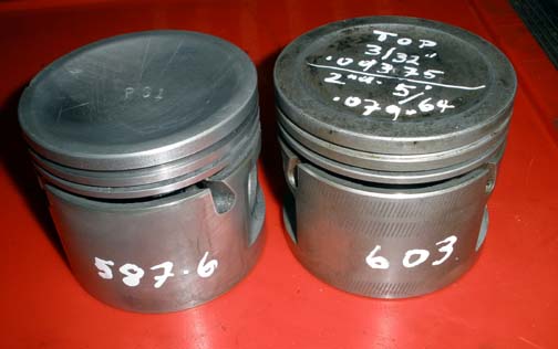 If you have access to a set of scales it's not that hard to mix and match pistons and pins to check for variations and even out the weights of the set. It's even worth checking the little end weight on the rods as this is the reciprocating end of the rod. Fit the rod with the lightest little end to the heaviest piston. This should provide another option if you don't want to physically remove weight from a piston. The pistons for the 3 litre sixes certainly are weighty items (1441gms)... double the weight of the pistons I posted above. * Warm the pistons with a hair dryer and then check the fit of the pins in the gudgeon. You'll probably find they fit and rotate very easily. V8 Pistons lock onto their rods by virtue of an interference fit so it's not an issue. As there are 2 points of gudgeon rotation on the 3 litre (rod small end & piston gudgeon) you really don't want them loose as the engine will end up with gudgeon rattle at idle speeds. On another note it's always worth checking for back ring clearance on the 2 top compression rings to ensure that they're not proud of the ring lands...not likely but worth checking as you go. This may be worth a read if balance issues are a concern. Piston Weights |
|
|
|
Post by djm16 on Dec 31, 2019 6:12:35 GMT
Thanks for your reply.
The 1441g is for a complete assembly of piston, rings, pin, rod, cap and bearing shells. Piston alone is 500-something. There was a heart stopping moment when I thought that JP pistons weighed 625g (as opposed to the original piston's 480g), then I realised the JP pistons had gudgeon pins in them!
Since the remaining assemblies are all within a gram, there really isn't an alternative assembly to swap the heavier piston with.
Rods and caps are interesting! There is up to 10g variation across the rods which has been evened out by careful selection of the caps weights. I did not attempt to compare balance points on the rods. Since the engine was pretty smooth before disassembly, I am guessing that the variable wt distribution between rods and caps is not significant.
I did at least match the heaviest piston with the lightest rod.
I am wondering whether I might lighten the gudgeon pin by 5g rather than take an air tool and burr to the piston! At least I can practice on up to 6 old pins first! This would be easy on a lathe, but I only have a drill press (cheap Bunnings type).
Thanks for the heads up about the upper ring going over the top of the machined section of the bore. I am pretty sure that it does not, but it would not hurt to check if I do decide to pull the piston again. I have not torqued any of the bearing caps yet.
Interesting read on the speed-talk forum, some of it quite heated, but without a firm conclusion as to whether 5g was significant, only an opinion that if it is worth doing, it is worth doing perfectly. I have read elsewhere that for an engine revving under 4,500 up to 1 oz of variation is acceptable. Different for an engine revving to 6,000.
|
|
|
|
Post by enigmas on Jan 1, 2020 2:56:02 GMT
Well that's good news that the pistons alone aren't at 1400 gms each...I was beginninig to wonder whether they were made of cast iron? If you can, keep the reciprocating weight as light as possible for obvious reasons. Interestingly there's even a case for over balancing engines with lighter pistons and rods. There's reference to a guy by the name of 'Smokey Yunick' on that link David...he was a very famous and well known race engine guru in the the early days of Nascar and Indianapolis raceway in the States. A very clever and intuitive engine builder. (Quote. "You don't race cars, you race the rule book") This was a guy who in one particular race ran a 2" diameter fuel line 11' long. It held an additional 5 gals of fuel. A week after his car won the race the rules were changed to prohibit fuel lines over 1/2" in diameter! I gather that you're not swapping any of the conrod caps? (They're each individually matched to their specific rod!) With reference to the top piston rings my comment was in relation to how far the ring sat into its ring land 'not' how far below the engine's deck surface. If pressed fully home into the ring land cavity...the ring should not protrude or sit proud of the piston surface. The compression rings (top & second ring require a back space or clearance. During the compression stroke 'cyl pressure' gets behind the ring forcing it against the cyl wall surface. This is how an effective cyl seal is created. The piston ring seal is not due to the mechanical springiness of the ring material but by cyl pressure behind the ring. You can lighten the piston by removing material from the gudgeon pin boss or from under the pins crown...if you can verify the thickness from an old piston. Don't do this unless you feel confident. 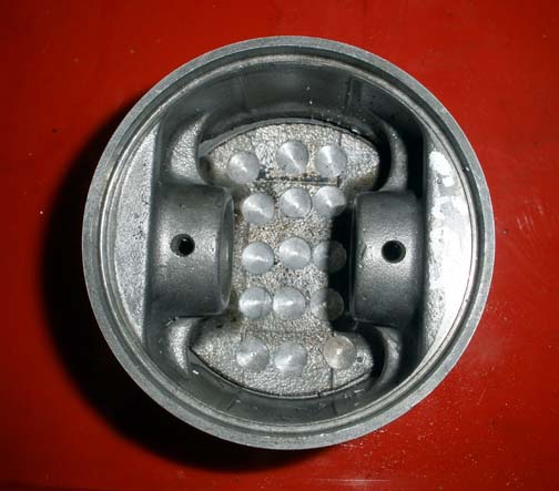 * Some trivia for anyone wanting an insight into Smokey Yunick |
|
|
|
Post by djm16 on Jan 13, 2020 6:51:20 GMT
Last week I did two things.
I reduced the wt of piston assembly number 1 by removing metal from the gudgeon pin. Two things I had not appreciated before, first that original Rover gudgeon pins vary hugely in wt, second that the pins supplied by JP are much thicker walled, and incidentally harder steel than the original. So taking 6g off with a die grinder burr made sense to me as I could not find anywhere on the piston where I felt comfortable removing material.
I also checked over the cam follower assembly. I had sent out the followers to be bushed, and had supplied one of the new rocker shafts to test fit. They came back, but the followers were pretty tight to get on the shaft, although free once in place. Minor relieving of the end of the shaft with a diamond file meant that the followers went on easier. I then unwrapped the longer rocker shaft, deburr it, and tried a cam follower on it. Darn, that's a lot of play! It felt distinctly loose. So I measured it, and measured the shorter shaft too for good measure (sorry).
Short shaft dia: 15.035mm, longer shaft 15.000mm. So about a thou and a half difference. I now worried that I had inadvertently commissioned a bunch of oversized bushings, but when I tried the three NOS cam followers, they had the same amount of play. So I am disappointed by the lack of consistency in the parts, but have tried to compensate by fitting the sloppiest followers to the short oversized shaft.
Boy it is exhausting being OCD.
|
|
|
|
Post by djm16 on Jan 15, 2020 11:15:10 GMT
Quick question. What would we seal the block plugs with?
Nothing?
Blue hylomar?
Silicon?
Something else?
|
|
|
|
Post by harvey on Jan 15, 2020 12:58:53 GMT
Quick question. What would we seal the block plugs with? Nothing? Blue hylomar? Silicon? Something else? If you mean the core plugs (and most other plugs come to that) I have always used Red Hermatite. |
|
|
|
Post by enigmas on Jan 15, 2020 13:14:33 GMT
I use this sealant David Loctite 518 * When you refer to the 'cam followers' do you actually mean the 'rocker' assembly? |
|
|
|
Post by djm16 on Jan 15, 2020 23:07:13 GMT
Thanks for the suggestions.
REPCO has this:
Loctite 518 Gasket Eliminator 50ml
SKU: A7929390
$44.99
They have got to be taking the piss out of the piss! No way I am paying $45 for a $1 part at REPCO.
Re Hermatite is now Red Hylotyte, and is more reasonably priced at Paddock Spares
Hylomar Hylotyte Red Semi Hardening Gasket and Jointing Compound
Price $5.91
Unfortunately shipping is priced at $33.
Re cam followers re rockers. According to Rover terminology, the exhaust rocker shaft carries exhaust rockers to open the exhaust valves, and cam followers to operate the pushrods. Confusing?
Now to see if I really did blow a head gasket on the P3 last night. As if I really need more repairs to do.
|
|
|
|
Post by enigmas on Jan 16, 2020 4:53:23 GMT
I buy loctite sealants from engineer supplies or engineer bolt suppliers. They're some of the best anerobic sealants available today.
As an aside I don't believe the Rover company invented the terms for 'Rocker' or 'lifter'. These terms have been around since well into the early part of the last century. Tappets and lifters whether solid or hydraulic generally do the same job and act directly against the rotating camshaft lobe. Tappet as a term is a hangover from side valve designs which often had the adjuster as an integral feature of the 'solid' lifter. Adjustments as you're probably aware when OHV designs displaced SV were generally taken up at the pushrod end of the rockers...called so because they rocked up and down.
The Rover 6 engine really is a mixed piece of engineering. Part OHV and part SV...and also utilizing roller followers...just like my 1942 SV harley Davidson engine.
Due to its complexity it's a very expensive power plant to refurbish...as you've found.
|
|
|
|
Post by djm16 on Jan 29, 2020 13:14:54 GMT
As I already mentioned, the cam followers / exhaust rockers that I had rebushed came out OK (except for the variation in the ocker shaft dia), the front cam bearing that I had machined from a (cheap) NOS raw unfinished bearing did not come out as well. I had to bite the bullet and buy a new finished one. $200 inc postage. Ouch!!
I assembled and installed the cam shaft yesterday, and immediately wished I had not. I knew that the front bearing was a little tight on the camshaft, I should have measured the clearance first, but I thought that the bearing halves would spread a bit in their nest in the block, as that was a little loose to start with. No such luck. The camshaft was quite stiff to turn despite the liberal assembly lube.
So tomorrow morning, I will be pulling the camshaft out again, and packing shims between the front bearing halves until I have a thou of running clearance.
Maybe getting it back in a second time will take less than the 3 hours the first time.
|
|
|
|
Post by djm16 on Feb 6, 2020 8:10:19 GMT
So I checked the cam bearings. They were not as I thought, not at all! The 70s were clearly not an era when you could buy spares from BL and expect them to be correct. I went over the camshaft and all the bearings and measured the dimensions. As you can see in the picture below, the camshaft is very close to 1 inch, minus a thou and a half. One inch would be 25.400mm. So 25.365 is one inch minus 35/1000 mm, and 1 thou is 25/1000 mm. This measurement is consistent across a couple of other spare camshafts that I have on loan for comparison, so I am confident this is as Rover intended.  The bearings however are all over the place. To record the internal diameter I have left out the "25." and recorded only the 1/100s of a mm. Thus, 25.410 is written on the bearing as "41". You can see internal diameters ranging from 25.37 to 25.43. That is equivalent to a range of clearances from 0.2 thou to 2.5 thou. Not only that, but it appears that a couple of the bearings are machined slightly oval. 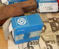 The clue of course should have been the BL emblem on the box that they came in. But realistically I doubt that the less-than-Rolls-Royce tolerances will make much difference in the long run. However, were I ever to do his again, I think I would go down the route of having the old bearings re-metalled by a specialist company. I suspect I would end up with more reliable tolerances if I did that. |
|
|
|
Post by djm16 on Feb 6, 2020 8:22:00 GMT
The next bit has taken me nearly all day, and that is to install the cam chain and set the cam timing. Since this engine is not a MkIII ,it does not have timing marks on the harmonic balancer, and since it is on an engine support and not on the bench, it is not possible to temporarily re-fit the flywheel so as to find the timing marks. I therefore had to manufacture a valve timing template to fit on the crankshaft before I could find TDC and EP etc. It only took me 3 hours and 3 goes to get it right. Part of the problem is that the information in the manual, with a nice diagram of the valve opening / closing sequence is from the viewpoint of the block. So a copy of the diagram mounted on the crankshaft ends up rotating the wrong way. My brain is getting too old to do mirror image angles in my head and get them right first time. I have marked TDC (360 degrees), and exhaust opening, closing and peak (red arc and arrow respectively). It is then remarkably hard to get the camshaft chain gear exactly right. Each time I thought I had it, checking again after rotating the crankshaft took up more slack than I thought I had, and had the cam timing 5 degrees late. I got there in the end after 2 hours of trial and error. Would 5 degrees have made that much difference? Probably not.  Before anyone asks, I will be putting a new lock-tab on the camshaft bolt. Don't want that falling off. |
|
|
|
Post by djm16 on Mar 3, 2020 14:16:37 GMT
I had delayed putting the head back on, remembering all the ways it can be done wrong. I did all the wrong ways last time! Most important is to place the fat O-ring over the water pump, and to install the generator mount. Now who would have thunk it that the generator mount cannot be installed once the head is on.
As I did not recall having any problem with the head before taking it off, I was planning just to put it back as-is, until I talked it over with a fellow Rover owner. His advice was sound: "at least replace the inlet guide O-rings". Fair enough thought I, and pulled all the valves out.
I wished I had not done so, as now I realised that not only did the O-rings need replacing, but the valves need refacing and the guides sleeving. The valve stems are well within spec, less than 1/10 thou wear at worst, but the guides had bell-mouthed to +4 thou.
I was looking the cost of K-line kits in Australia, and finding out why I did not buy one last time I had a head off. The price - around $1400 all-in + GST. Had I bought one when I had my first head off, I would have broken even by now, but I was not sufficiently confident then to do the job.
Anyway I will be taking the head down to a machine shop that does K-liners.
|
|
|
|
Post by djm16 on Mar 26, 2020 4:14:36 GMT
We have the head back from the machine shop. A nice job done, and I am glad that I did not tackle this one myself as it is so much easier with the right tools. A very modest fee included dressing the valves and valve seats. He also very carefully left the O ring slot free. We had a chat about the O-rings, and I was pleased to learn that I am not the only one who has trouble getting them in without damage. Typically the valve stem slices a sliver of rubber off the O-ring as it is pushed up the guide for the first time. If you have to take the valve out again, you lose another sliver too! Well I was determined to do this without causing damage to the O-ring. The first difficulty is getting the O-ring seated in the first place. This was my technique. First, I placed a smidgen of silicon grease on the O-ring before insertion. 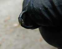 I then used two valves to guide the O-ring into its slot (one above and one below). This did not always work immediately, some O-rings were very reluctant to stay in their slot. Attachment DeletedThe O-ring still is not fully seated, only in place. So my next step was to insert a long taper to spread the O-ring out. Ideal for this was an old water-color brush. 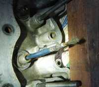 |
|
|
|
Post by djm16 on Mar 26, 2020 4:20:16 GMT
The major cause for damage to the O-rings on inserting the valves is the presence of sharp edges on the valve stem. So with a fine diamond hand file, I dressed chamfer on the top of the valve, and also the leading and trailing edges of the groove where the collets sit. I don't know if you can make out this in the pictures:   With this preparation, the valves went home easily with a sharp slap to the bottom, with no damage to any of the O-rings, |
|


