|
|
Post by johnwp5bcoupe on Jul 6, 2020 11:02:34 GMT
I get your theory Vince the Rose Joint I was thinking of is a Spherical one this would give movement in all directions but not directly up and down! just one of my ramblings  |
|
|
|
Post by enigmas on Jul 6, 2020 11:14:29 GMT
Hey...I think we both like solving problems John.  |
|
|
|
Post by Jens Munk on Jul 6, 2020 12:23:02 GMT
Thanks to all for your valuable input. Since the basics ought to be right, the next two things I am going to try are:
- Ensure the u-joint spider I replaced is seated properly.
- Limit the movement of the center bearing console.
As for 2, the special shaped "support stud" number 13 below, my plan is to make a cylindrical rod fitting snug into the rubber bushing 14, that should limit the movement significantly but still have a bit of rubber cushion between the metal. Probably not a permanent solution but hopefully enough to show if we are looking at the right spot.
The spring items 29 - 34 makes to sense to me.
|
|
|
|
Post by Jens Munk on Jul 6, 2020 12:27:46 GMT
Yes, it can move in all directions.
And yes, this appears to be a Pandora's box. Obviously not that rare a problem and pretty irritating too.
Jens...can you physically move the centre coupling up/down or sideways in its centre mount? An answer of either Yes or No will tell you whether the issue is there or else where in the system. Consider the first half of the tailshaft up to the centre coupling as a straight line or extension with the crankshaft axis. Don't think of it as part of the tailshaft...think of it as the rear transmission flange/coupling. Would you fit a jelly like mount at the rear of the transmission? As for the first half of the tailshaft running dead straight and 'supposedly' wearing the universal joint rollers out prematurely...it really ain't gonna happen in a day or two! Nothing in a transmission assembly is mounted that rigidly or metal to metal. It all moves about to a degree under general driving conditions. * It's interesting to note that once the drive shaft issue was brought to light it opened up something of a pandora's box with regard to other P5 owners also have similar experiences with their cars. |
|
|
|
Post by enigmas on Jul 6, 2020 13:54:27 GMT
It looks like you're beginning to nail the problem Jens. From what I recollect with the original setup on my coupe item 14 (the hollow rubber bush) was also badly grooved where it locates in the bearing carrier (item 12). The internal circumference edges of the 2 locating holes (item 12) that the rubber bush is held externally by tend to erode the bush at the contact points, creating a valley and inducing even more play/slop in the assembly. The original bushes on my car were also well past their use by date as the composition of the rubber had also degraded markedly. Perhaps turning-up a couple of polyurethane sleeves on a lath might provide a viable solution for the original centre mount system. The material is certainly denser and firmer than a rubber sleeve. urethanesp.wordpress.com/2013/02/07/is-polyurethane-really-better-than-plastic-or-rubber/ |
|
|
|
Post by johnwp5bcoupe on Jul 6, 2020 14:11:09 GMT
This is a useful site link |
|
|
|
Post by Jens Munk on Jul 6, 2020 21:59:36 GMT
Unfortunately that didn't make any difference 
It appears that the 13 support stud can be replaced by a piece of 1/2" water pipe and a 3/8" bolt so the 14 rubber bushing sits without any space under it and hence locating the bearing carrier much tighter. However when approaching 100 km/h it starts to vibrate like before with the stock support studs. Anyway, definitely worth a try.
I am going to sleep on it now, but I think my next step is to address the +/- 5 degree angles on the rear u-joints. While the flanges are parallel and supposed to cancel out, it is quite a bit of strain on the shaft and its sliding joint.
It has the heavy-duty 5-leaf springs ever since I realized one of the former springs had a broken leaf. They are sitting about 2" higher that what I can judge from factory photos and height numbers in the WSM, so I recently swapped to the new 7-leaf that give the correct height. No notable difference in vibration with just myself in the car, but loaded with passengers and luggage it becomes stressful. Getting a proper electronic spirit level checking and adjusting the angles with shims at the transmission mount, 2 degrees wedges at the springs and fine tuning at the center bearing helped quite a bit, but the vibrations over 100 km/h are now apparent. I basically didn't go that fast before.
So next is to put the 5-leaf springs back and adjust the angles correctly. All angles should then end up below 1 degree.
It looks like you're beginning to nail the problem Jens. From what I recollect with the original setup on my coupe item 14 (the hollow rubber bush) was also badly grooved where it locates in the bearing carrier (item 12). The internal circumference edges of the 2 locating holes (item 12) that the rubber bush is held externally by tend to erode the bush at the contact points, creating a valley and inducing even more play/slop in the assembly. The original bushes on my car were also well past their use by date as the composition of the rubber had also degraded markedly. Perhaps turning-up a couple of polyurethane sleeves on a lath might provide a viable solution for the original centre mount system. The material is certainly denser and firmer than a rubber sleeve. urethanesp.wordpress.com/2013/02/07/is-polyurethane-really-better-than-plastic-or-rubber/ |
|
|
|
Post by enigmas on Jul 6, 2020 23:47:11 GMT
Jens have you tried disconnecting the tailshaft at the transmission flange to ensure that the vibration isn't emanating from the engine or transmission.
Transmission.
Worn transmission bushes on the input shaft to the torque convertor.
Worn bushes will allow the input shaft to slop about.
Out of balance torque convertor or drive plate. (A fully reconditioned torque convertor I fitted was found to be out of balance)
Rear Wheels/Rear Brake Assemblies/Final drive.
* You really need to check these so that they can be discounted.
1. Are the wheels & tyres in balance and or running true. Jack the car up, remove rear wheels and free rev the engine in gear.
2. Brake drums. Theses are large cast iron lumps. As above in 1.
3. Bent rear half shafts. Not likely but possible. Observe flange rotation with engine trans engaged.
|
|
|
|
Post by djm16 on Jul 7, 2020 1:33:55 GMT
when I was investigating the vibration on mine, I had the rear up on axle stands, and the wheels off (to remove unbalanced wheels as a confounding factor).
I ran the engine up to the speed that gave me the most vibration, and went underneath with a marker pen. With a bright light, the propshaft was visibly running eccentric at one end. That gave a clue to where one of the problems lay - with the rear UJ. when that was correctly aligned and the prop shaft ran true, but still vibrated, the marker pen showed where the propshaft was most eccentric. I cannot explain why, but I am sure that the maths is correct, but placing a weight at 90 degrees to the eccentricity removed the residual vibration problem.
Have you considered sticking a jack under the centre mount (with a piece of rubber to cushion it) to mimic Enigma's proposal to stiffen up the centre mount?
PS, I have just remembered why the propshaft on my P3 vibrated so badly. A previous owner had split off the rear UJ from the diff flange using a chisel, and had thrown up a tiny burr on the flange. That had caused the UJ to run a few thou out of true, and no amount of balancing would fix it until the burr was filed back.
|
|
|
|
Post by enigmas on Jul 7, 2020 3:49:02 GMT
I found this first short video on driveshaft angles and correcting out of phase alignment. What I like about this particular video and the young man presenting it is the clarity of the technical explanation through the use of simple hand drawn diagrams.
None of the video presentations that relate to measuring positive and negative 'slopes/angles' that I've seen actually explain the theory behind the physics of the 'hookes' type universal joint when it is rotated at an angle (it both speeds up & slows down). This video does.
* The magnetic angle finder is a simple and inexpensive tool available in most tool shops.
If you really what to understand the physics behind the action of a hookes type universal joint the brief animated video below explains/illustrates it both simply and clearly.
|
|
|
|
Post by Jens Munk on Jul 7, 2020 6:49:29 GMT
Yes, it is probably time to do some actual vibration measurements to locate the culprit. Since I do in fact have an old but functional vibration meter laying around, how about using with the car on stands?
As for the transmission, it was rebuild a couple of years ago with assistance from John Wallet. Among other things all bushings were replaced and so was the converter. The drive plate has also been balanced when I had the engine balanced.
Wheels and brakes should be OK, but will check. Jens have you tried disconnecting the tailshaft at the transmission flange to ensure that the vibration isn't emanating from the engine or transmission. Transmission. Worn transmission bushes on the input shaft to the torque convertor. Worn bushes will allow the input shaft to slop about. Out of balance torque convertor or drive plate. (A fully reconditioned torque convertor I fitted was found to be out of balance) Rear Wheels/Rear Brake Assemblies/Final drive.* You really need to check these so that they can be discounted. 1. Are the wheels & tyres in balance and or running true. Jack the car up, remove rear wheels and free rev the engine in gear. 2. Brake drums. Theses are large cast iron lumps. As above in 1. 3. Bent rear half shafts. Not likely but possible. Observe flange rotation with engine trans engaged. |
|
|
|
Post by Jens Munk on Jul 7, 2020 6:50:38 GMT
Good video and this is exactly what I have done.
I found this first short video on driveshaft angles and correcting out of phase alignment. What I like about this particular video and the young man presenting it is the clarity of the technical explanation through the use of simple hand drawn diagrams. None of the video presentations that relate to measuring positive and negative 'slopes/angles' that I've seen actually explain the theory behind the physics of the 'hookes' type universal joint when it is rotated at an angle (it both speeds up & slows down). This video does. * The magnetic angle finder is a simple and inexpensive tool available in most tool shops. If you really what to understand the physics behind the action of a hookes type universal joint the brief animated video below explains/illustrates it both simply and clearly. |
|
|
|
Post by Jens Munk on Jul 17, 2020 12:36:30 GMT
Update....
First of all checking the full assembly with the vibration sensor at the transmission joint and center joint. Transmission joint didn't really show anything but the readings at the center joint matched the magnitude of the felt vibrations.
Starting from the front end by disconnecting the prop shaft from the transmission as the first step. Things were fine except that the big steering wheel has some resonances and vibrates a bit at certain RPMs although nothing else seems to misbehave. It is what it is.
Next, attaching the front shaft only with the sensor at the center joint and to my somewhat surprise, this is where the vibrations are. My suspicion was the rear shaft with its two u-joint operating at larger angles and the sliding joint, but apparently the front shaft is the main culprit. Also, I have had the whole assembly balanced not too long ago, but must have been a bad job.
So off to another drive shaft balancing shop to have the two shafts balanced separately and together and voila - vibration gone!
In conclusion, it was out of alignment as well as out of balance. The alignment required 8 mm lift of the transmission mount (shim plates), 2 degree rear spring wedges and fine tuning at the center joint with a digital spirit level. Balancing required the right shop.
Under strong acceleration at low speeds and take off, there is a bit of vibration, but I suspect this to be either the soft center bearing support, that I put back in, that shifts under high torque and/or the +5 degree (matching) angles of the rear shaft joint. In any case it's tolerable for now and can await investigation for another sunny day.
|
|
|
|
Post by johnwp5bcoupe on Jul 18, 2020 8:58:26 GMT
The Diff nose angle may alter on take off if you accelerate hard Jens due to the axle wind up!
Just a thought!
|
|
Deleted
Deleted Member
Posts: 0
|
Post by Deleted on Jul 18, 2020 9:23:24 GMT
when I was investigating the vibration on mine, I had the rear up on axle stands, and the wheels off (to remove unbalanced wheels as a confounding factor). I ran the engine up to the speed that gave me the most vibration, and went underneath with a marker pen. With a bright light, the propshaft was visibly running eccentric at one end. That gave a clue to where one of the problems lay - with the rear UJ. when that was correctly aligned and the prop shaft ran true, but still vibrated, the marker pen showed where the propshaft was most eccentric. I cannot explain why, but I am sure that the maths is correct, but placing a weight at 90 degrees to the eccentricity removed the residual vibration problem. ......................................... I did pretty much the same on my transit,its how some balancers work using pressure sensors to locate the heavy spot. I finished off mine by trial and error with a jubilee clip. The flexible mount on the transit is very flexible,if you think about it some movement is necessary to stop vibrations being transmitted to the body. |
|
|
|
Post by enigmas on Jul 18, 2020 10:57:02 GMT
when I was investigating the vibration on mine, I had the rear up on axle stands, and the wheels off (to remove unbalanced wheels as a confounding factor). I ran the engine up to the speed that gave me the most vibration, and went underneath with a marker pen. With a bright light, the propshaft was visibly running eccentric at one end. That gave a clue to where one of the problems lay - with the rear UJ. when that was correctly aligned and the prop shaft ran true, but still vibrated, the marker pen showed where the propshaft was most eccentric. I cannot explain why, but I am sure that the maths is correct, but placing a weight at 90 degrees to the eccentricity removed the residual vibration problem. ......................................... I did pretty much the same on my transit,its how some balancers work using pressure sensors to locate the heavy spot. I finished off mine by trial and error with a jubilee clip. The flexible mount on the transit is very flexible,if you think about it some movement is necessary to stop vibrations being transmitted to the body. Very brave you two!  No way am I going to lay under a car with a powered-up spinning tailshaft and a marker pen in hand! That's definitely a job for someone expendable. I admire the desire (if not particularly the manner) to rectify the problem though. |
|
|
|
Post by enigmas on Jul 18, 2020 11:51:24 GMT
The Diff nose angle may alter on take off if you accelerate hard Jens due to the axle wind up! Just a thought! Jens...I have these low pressure polyair 'airbags' (an overload device) fitted to my car. Note the positioning on the leaf spring just in front of the rear axle. This also resists axle wind-up under heavy torque loading and assists in maintaining the correct pinion angle 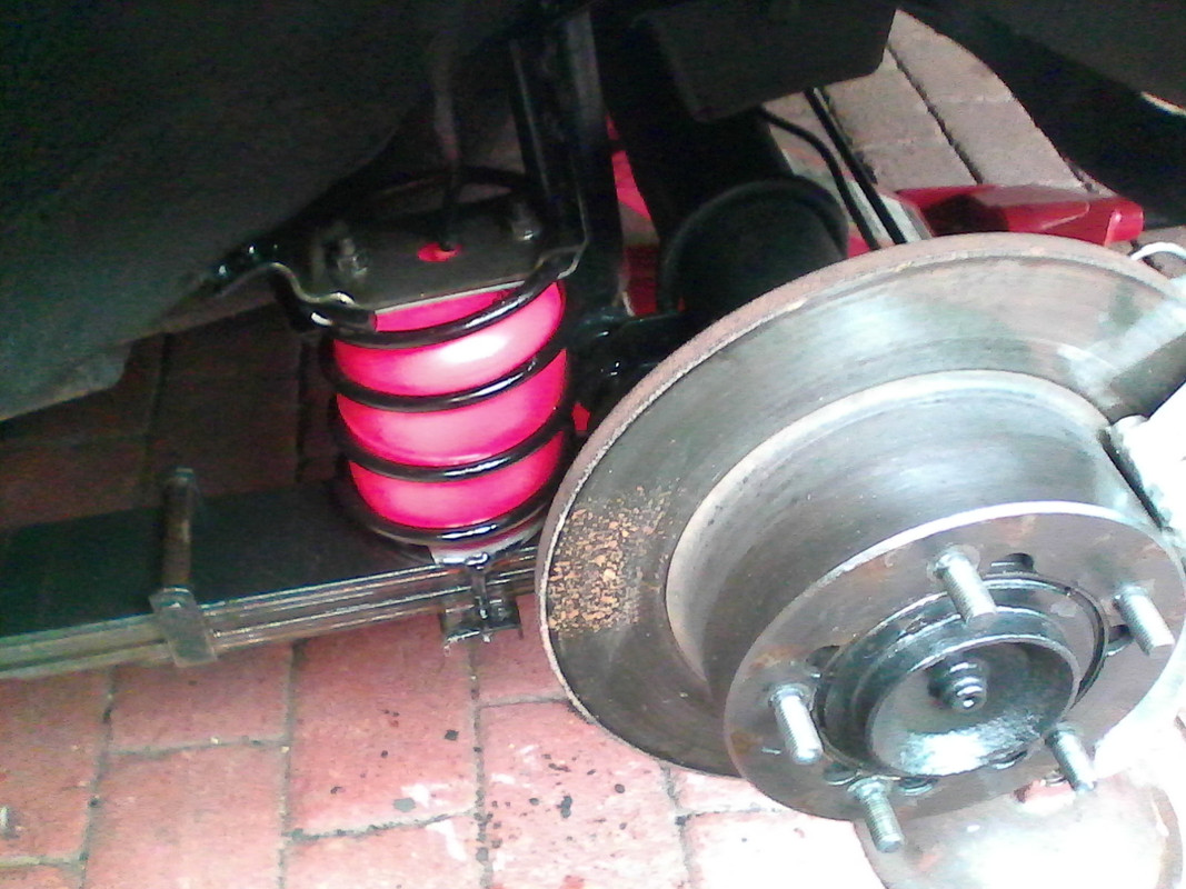 * You could also fabricate a simple anti-tramp bar under the front half of the leaf spring as an experiment to help maintain the correct pinion angle. |
|
|
|
Post by Jens Munk on Jul 19, 2020 10:05:55 GMT
Absolutely, and I am sure it does. At steady speed and on stands, it's fine.
The Diff nose angle may alter on take off if you accelerate hard Jens due to the axle wind up! Just a thought! |
|
|
|
Post by enigmas on Jul 19, 2020 23:53:00 GMT
You can also try biasing the diff nose down a couple of degrees Jen to counter the windup effect under heavy torque loading. Finding a compromise angle between torque loading both on and off.
* Unfortunately some of it will still be attributable to the centre mount if it's too flexibly mounted.
|
|
|
|
Post by Jens Munk on Jul 20, 2020 21:58:48 GMT
Next and hopefully the final update.
The last alignment after the shafts had been properly balanced was 8 mm shims under the transmission mount, 2 degree wedges at the springs and the center bearing adjusted to make the flange at the center in parallel with the pinion flange. Fine at high speed and low to no load. Unfortunately vibrations at lower speed and strong acceleration, which is one of the reasons we like to drive these V8 automatics.
Back to the math and computer to understand the issue better. The problem is that although rotation fluctuations at the joints at the rear shaft cancels out when the angles at the two joints are the same, the fluctuation at the shaft itself increases rapidly with the joint angles. Not exponential, but pretty severe as can be seen in the chart below. Angles lower than 1 degree or so only have negligible rotational deviation, but the setup had about 6 degrees. So at no load or on stands in the shop, it works, but when the rear axle twists in the leaf springs from all the V8 torque, the pinion lift and gets a larger angle than the center joint.

So instead of blindly focusing on getting the angles of the rear axle joints the same, trying to get all joint angles as small as possible, is next. More specifically: Keep the 8 mm shim at the transmission mount, remove the 2 degree rear axle wedges and pushing the center joint as far up as possible, the angle across the transmission joint becomes 0.6 degrees, center joint 3.1 degree and pinion 1.3.
The difference is amazing. Vibrations are gone and I am a much happier camper.
If somebody else should fancy trying my prop-shaft calculator, please let me know and I can tidy it up for use by other people than myself.
|
|
|
|
Post by enigmas on Jul 21, 2020 0:05:59 GMT
I find the charts fascinating Jens but as colourful and theoretically enlightening as they are they solve nothing. I'm not wanting to rain on your parade or methodology but there's something fundamentally wrong with your setup that unfortunately you're not seeing and perhaps a set of fresh eyes would see. The 3.5 litre V8 is not the torque monster of V8 engines although it is a sweet little engine. If your car is getting a vibration at low speed under torque something in the system is moving out of alignment. My money is still on the centre support. I truly doubt that your rear leaf springs are winding up otherwise it would be obvious on other Rover P5Bs and it's not AFAIK. Why not try some temporary 'lateral thinking' solutions to identify the cause? For instance, fabricate a basic set of anti tramp bars (square section box tube steel and flat strap steel brackets). Even if it locks the front half of the leaf spring...you can then discount one element as a cause of your issue. Here are a few pix of anti tramp bars. The yellow set is an easy fabrication purely to assess windup if any. The rubber snubber could be replaced with an adjustable bolt so no wind-up is allowed at all. Use it as diagnostic tool not a permanent fix. 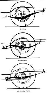 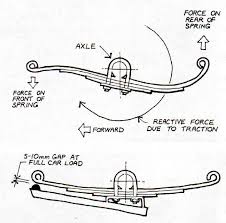 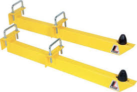 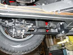 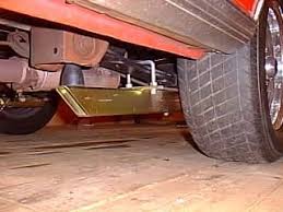 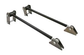 |
|
|
|
Post by djm16 on Jul 21, 2020 0:39:38 GMT
I am glad that you are getting somewhere. As is often the case, there are multiple contributors, but I bet that if you were to lock up the centre mount temporarily, the vibration under load would go away. My guess is that with 3 degrees at the centre jt, the centre bearing will precess under load.
A second confirmatory test would be to load a dozen 20kg bags of sand into the boot until the angle between front and rear propshafts is of the order of 0.5 degrees, and again see if the vibration has gone.
Or if I was being really rude, I would suggest putting my wife and MIL on the back seat as she is not reading this thread. But of course being happily married, I could not possibly say such a thing.
|
|
|
|
Post by Jens Munk on Jul 21, 2020 6:20:25 GMT
While you may not like my approach in resolving this issue, please don't underestimate the result. It works! And there are no modifications from what Rover came up with back then - just shims, proper balancing and center bearing adjustment.
I am very curious to the actual angles of your setup. I am also very curious to the angles as delivered from Rover as new, but we will probably never figure out the latter, since it is not mentioned in the WSM.
I find the charts fascinating Jens but as colourful and theoretically enlightening as they are they solve nothing. I'm not wanting to rain on your parade or methodology but there's something fundamentally wrong with your setup that unfortunately you're not seeing and perhaps a set of fresh eyes would see. The 3.5 litre V8 is not the torque monster of V8 engines although it is a sweet little engine. If your car is getting a vibration at low speed under torque something in the system is moving out of alignment. My money is still on the centre support. I truly doubt that your rear leaf springs are winding up otherwise it would be obvious on other Rover P5Bs and it's not AFAIK. Why not try some temporary 'lateral thinking' solutions to identify the cause? For instance, fabricate a basic set of anti tramp bars (square section box tube steel and flat strap steel brackets). Even if it locks the front half of the leaf spring...you can then discount one element as a cause of your issue. Here are a few pix of anti tramp bars. The yellow set is an easy fabrication purely to assess windup if any. The rubber snubber could be replaced with an adjustable bolt so no wind-up is allowed at all. Use it as diagnostic tool not a permanent fix. |
|
|
|
Post by Jens Munk on Jul 21, 2020 6:31:14 GMT
Multiple problems with approx. the same effect are a real pain. Been there too many times both professionally and in hobby life. Heavier gravitational load is next to try - fingers crossed.
Also being happily married (for 30 year next Tuesday), the wife is a common load - often behind the steering wheel and not the rear seat.
I am glad that you are getting somewhere. As is often the case, there are multiple contributors, but I bet that if you were to lock up the centre mount temporarily, the vibration under load would go away. My guess is that with 3 degrees at the centre jt, the centre bearing will precess under load. A second confirmatory test would be to load a dozen 20kg bags of sand into the boot until the angle between front and rear propshafts is of the order of 0.5 degrees, and again see if the vibration has gone. Or if I was being really rude, I would suggest putting my wife and MIL on the back seat as she is not reading this thread. But of course being happily married, I could not possibly say such a thing. |
|
|
|
Post by enigmas on Jul 21, 2020 13:03:27 GMT
Jens there are all sorts of options available to you to sort the vibrations that are seemingly emanating from your drives shaft assembly. Unfortunately for reasons unkown you may have to deviate from the Factory arrangement to resolve the issue. Perhaps the question you need to ask is...If the vibration issue wasn't there when you first purchased and drove the car...then what has changed under your ownership? I've really got no excuse with my car as I introduced all the mechanical changes/alterations!  There were quite a few issues to resolve when I both recommissioned and up-engined my Mk3 to a 4.4 litre P76 motor, including the driveline/tailshaft assembly. The car was purchased in a very run down condition with the most of the drive train requiring a full rebuild. The P76 engine sits lower than the P5B V8 as I utilized the MK3 front subframe and built my own mounting system. It does hook up to the original BW35 trans case but has a custom made rear mount. The original Rover differential unit has had a Salisbury centre section adapted to it running a 4 pinion 2.92:1 ratio. It still uses the Rover half shafts. What I wasn't told at the time of the conversion (by the diff specialist) was that the pinion would be slightly offset to the PS. This did cause issues. Vibration at take off speed when under load...such as when taking off up a steep gradient. No vibration was felt at speed. Also, under heavy, quick acceleration at times there would be an audible thump as the centre mount would hit the trans tunnel. Changes introduced. * Initially the complete tailshaft assembly was rebalanced. * The centre bearing mount was modified in 2 ways. Tapered rubber bushes with matching mounts (welded in where the former factory rubber tube mounts fit) were used to restrain the centre mount from torque induced movement. The mount was also offset to the PS. * The whole tailshaft assembly runs at at a slightly acute angle within the tunnel to align with the offset differential pinion. These modifications resolved both the low speed torque induced vibration and the centre mount moving out of alignment under sudden acceleration. |
|


