|
|
Post by Jens Munk on Jul 2, 2020 23:07:33 GMT
The propeller shaft is driving me crazy. It vibrates or rumbles, and attempts to measure angles and correct accordingly for the most just makes it different. I wonder what the correct angles are supposed to be, since the workshop manual doesn't even mention. Does somebody know?
It is important that the angles match up, and with an 8 mm shim under the transmission, 2 degrees wedges between the rear axle and springs lifting up the pinion, I can adjust the center bearing to get the front prop shaft at the same angle towards horizontal as the pinon shaft. The angle of the transmission joint is 0.6 degrees. And yes, it is phased correctly.
This works reasonably okay up to about 100 km/h / 60 mph, but over this speed it vibrates badly. My prime suspect is the angles of the u joints of the rear shaft. Although identical and supposed to cancel out, they are 5.6 degrees. I read somewhere that 3 is about max.
So I really wonder what the correct angles are on your vibration free Rovers?
I am also puzzled why it needs such thick shims and wedges to just get somewhat within range. Could it be the sub-frame bushes and/or the sub-frame itself?
|
|
|
|
Post by enigmas on Jul 2, 2020 23:26:29 GMT
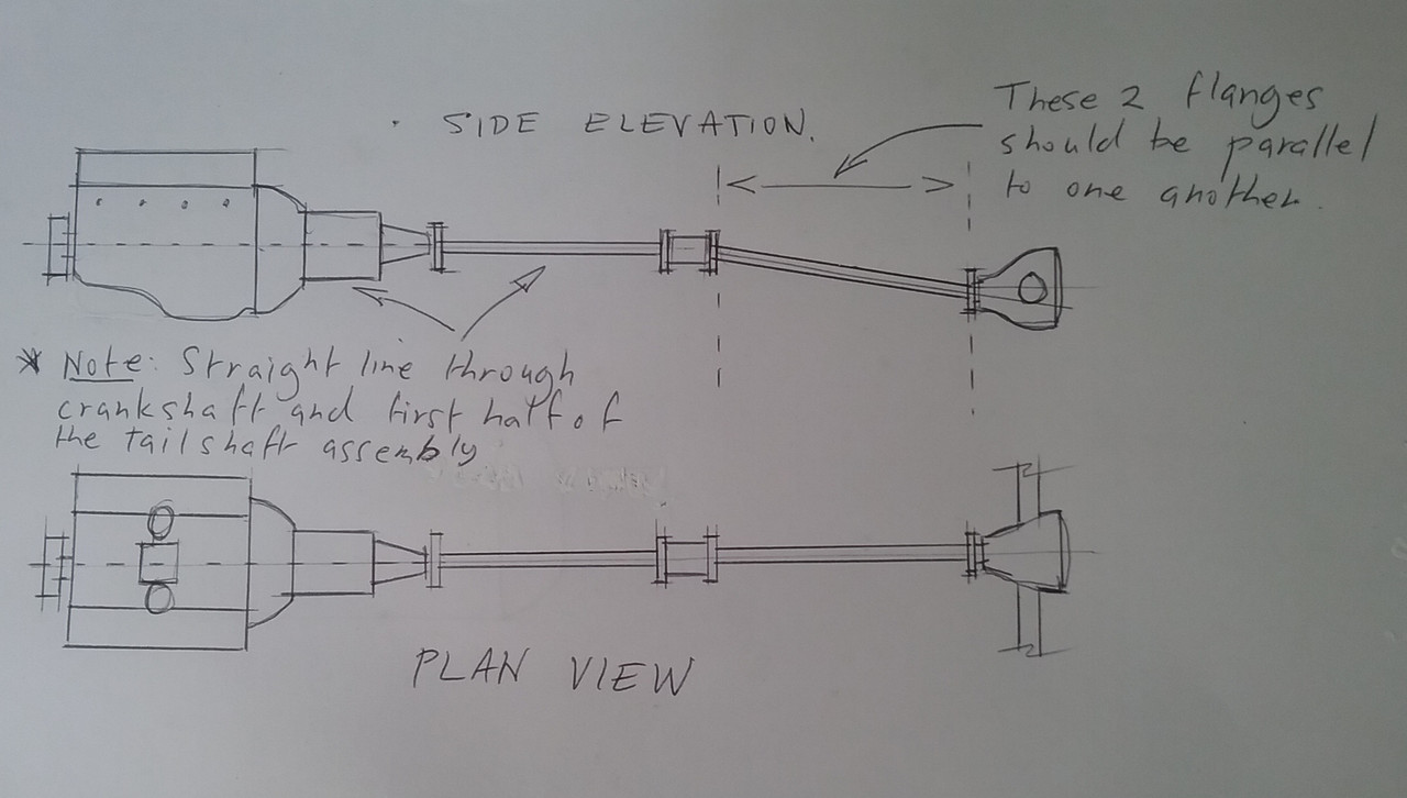
You're over thinking this Jens and most likely have a throbbing head ache by now!  This setup works for me and is how I setup my P5 coupe. 1. Ensure that the whole assembly from the gearbox flange to the tailshaft flange is a straight line when viewed from directly above. 2. The first half of the assembly (gearbox flange to centre universal joints) should be in alignment with the crankshaft. Imagine it as a perfect straight line through the crankshaft and first half of the tailshaft. 3. The angle of the differential pinion flange needs to match the angle of the centre bearing flange from the vertical. For example. Both flanges can be at 90° to the ground/parallel to one another (if measured on a flat horizontal surface) even though the second half (rear part) of the tailshaft assembly may be at a downward angle to the differential pinion flange.
* The centre bearing should not flop about on its mounting either...so evaluate it carefully to ensure the assembly is secure and positioned correctly.
* The rear 2 shaft flanges do not need to be 'vertically' parallel to one another but must be parallel. See below. Eg. / / or \ \ or | |
Do this and you won't have any tailshaft vibrations.
 |
|
|
|
Post by Jens Munk on Jul 3, 2020 6:09:09 GMT
Thanks Enigmas, and maybe not a physical headache then not so much sleep tonight.
Anyway, the way you describe it, which is much simpler than my description, is exactly what I have obtained. All the flanges are parallel within 0.5 degrees. My concern is that to achieve that, the angles across the center and rear joints are 5.8 degrees (in either direction, of course). What I have found out in cyberspace, is that the max joint angle should be kept below 3 degrees to avoid vibrations at higher rpm's.
BTW, the rear axle sits above the line of the engine-transmission-front shaft line and not below as in your sketch. The engine-transmission inclination is 4.7 degrees in my car with fairly new and undistorted engine and transmission rubber mounts.
|
|
|
|
Post by enigmas on Jul 3, 2020 7:34:39 GMT
Interesting Jens...my P5s tailshaft sits as per the side elevation diagram.
As an aside I re-engined my MK3 P5 with a P76 V8 (4.4 OZ version of the Rover 3.5 V8.) It also has a modified diff running a 2.9:1 differential. The pinion is offset slightly to the PS...not in exact centre. This is just a feature of the differential which was fitted to many OZ Ford cars.
The slight offset initially caused an annoying vibration at low speeds in load situations...eg. taking off up a steep hill.
To resolve the issue I offset the centre bearing support slighty to the PS. So now the whole tailshaft runs at a slightly oblique angle from the trans flange to the differential flange.
* I also modified the centre mount. I tend to think the factory mount is a woeful design allowing the centre coupling to move about like jelly...especially under torque loading.
* I do believe the first half of the tailshaft has to be in alignment with the crankshaft. Consider it as one component in a straight line. There's no out of phase issues simply because it's running in a dead straight line.
Anything that's out of phase or causing vibration issues is emanating from either the centre mount (it's allowing unrestricted movement) or the second half section of the tailshaft.
Whether the diff flange is above or below the centre bearing support is irrelevant as long as the centre bearing flange (the one near the sliding yoke) and the diff pinion flange are parallel.
The working angle of the tailshaft can be more than 3°...take a look at most truck tailshafts and the angles they work at. Most can be viewed from the DS of your car whilst in traffic. If the opposing flanges are parallel no matter the angle of the universal joints the out of phase issues cancel each other out.
Most modern split tailshafts in cars/trucks today run a constant velocity joint at the centre bearing...the P5 doesn't (old tech) hence the confusion when assessing it or trying to figure out how it works!
Modern constant velocity centre bearings in tailshaft configurations are also mounted more securely than the jelly like configuration the P5 uses.
* One last point to consider is torque reaction on the pinion flange. This moves up or down when either power is applied or when your foot comes off the throttle under coast situations. The front of the leaf spring may be flexing up and down (leaf spring wind up?)
Biasing one way or the other can often correct this. You could also try locking the front half of the spring pack with 2 pieces of steel strapping and suitable bolts
|
|
|
|
Post by johnwp5bcoupe on Jul 3, 2020 8:57:29 GMT
All great stuff Vince  Just check the rear half of the prop that the Arrow is lined up with the reference mark Jens? |
|
|
|
Post by johnwp5bcoupe on Jul 3, 2020 9:01:37 GMT
Thanks Enigmas, and maybe not a physical headache then not so much sleep tonight. Anyway, the way you describe it, which is much simpler than my description, is exactly what I have obtained. All the flanges are parallel within 0.5 degrees. My concern is that to achieve that, the angles across the center and rear joints are 5.8 degrees (in either direction, of course). What I have found out in cyberspace, is that the max joint angle should be kept below 3 degrees to avoid vibrations at higher rpm's. BTW, the rear axle sits above the line of the engine-transmission-front shaft line and not below as in your sketch. The engine-transmission inclination is 4.7 degrees in my car with fairly new and undistorted engine and transmission rubber mounts.
Where are you taking the CV joint angle Jens? |
|
|
|
Post by Jens Munk on Jul 3, 2020 14:13:14 GMT
Hi John,
I am using an electronic spirit level.
The two shafts are measured directly. The pinion angle is measured on the flange and the engine/transmission angle on the flat Rover valve covers. When you think about the latter, they are parallel to the crankshaft. The U-joint angles are the difference between the angles of the shafts on either side.
Where are you taking the CV joint angle Jens? |
|
|
|
Post by Jens Munk on Jul 3, 2020 14:14:19 GMT
Yes. All great stuff Vince Just check the rear half of the prop that the Arrow is lined up with the reference mark Jens? |
|
|
|
Post by Jens Munk on Jul 3, 2020 14:47:10 GMT
How have you modified the center mount? It is kind of wobbly. * I also modified the centre mount. I tend to think the factory mount is a woeful design allowing the centre coupling to move about like jelly...especially under torque loading. |
|
|
|
Post by lagain on Jul 3, 2020 19:05:58 GMT
Have you had it balanced ?
For decades my car would get up to speed and vibrate, nothing I did fixed it until I had the prop shaft balanced.
From memory it was the rear section, there was a weight on the front but nothing on the back. I took it to a chap at East Grinstead and he put it on his balancing machine which showed that it was 'out' he welded a weight onto it and since then she has been super smoooooooooooth
|
|
|
|
Post by enigmas on Jul 3, 2020 23:43:35 GMT
How have you modified the center mount? It is kind of wobbly. * I also modified the centre mount. I tend to think the factory mount is a woeful design allowing the centre coupling to move about like jelly...especially under torque loading. Centre Mount Issues. (experienced by my coupe) 1. The mount as designed appeared to give little stability to the mass and length of the tailshaft assembly. (i) I could easily physically move it about by hand in most compass directions. (ii) It would at times thump the floor tunnel under heavy torque loading.
This meant the whole assembly was moving upwards and obviously out of alignment at these times Note item 12 in the illustration below.
The assembly is held by 2 long hollow rubber bushes on 2 scalloped pins and a light spring (? WTF!) * This part of the assembly is the primary cause of unrestrained movement.
Modification: I cut off and welded lower shock absorber bush mounts from an old shock absorber (not the P5 version...too large) into each hole.
These mounts accept small conical bushes (2 per mount) and hold the assembly firmly but still allow very slight orientation movement.
* The light spring was dispensed with as it provides no viable function.
 |
|
Deleted
Deleted Member
Posts: 0
|
Post by Deleted on Jul 4, 2020 8:53:39 GMT
As an aside I remember at college being told that it was beneficial for a universal joint to 'flex' slightly to allow the grease and rollers inside to redistribute.
Normally the movement of axles,engines etc would provide this movement.
When I changed to an overdrive gearbox on my transit the split prop shaft was shortened and the the axle end had to be swapped over as the flanges are completely different. I used a jubilee clip to dampen a vibration which came on exactly at 30 mph but vanished at 35. I spent many happy moments underneath moving it round and up and down the shaft.
|
|
|
|
Post by djm16 on Jul 4, 2020 14:24:07 GMT
I have spent many a happy hour underneath P3, P4 and P5 working on the propshaft.
I am aware of at least four ways a propshaft problem can lead to vibration.
1) the flange angles. They all need to be parallel to each other. If they are not parallel, then the out of parallel flange will accelerate and deccelerate with each rotation on order to keep up with a constantly turning propshaft. I know you have worked on these.
2) the propshaft itself can be out of balance. But unless you have lost a weight, it seems a little improbable as they were balanced by Rover.
3) a stiff UJ will introduce vibration. Stiff because it is old and dry, or stiff because when it was installed, the mechanic did not give each of the four end cap carriers a gentle tap with a mallet to ease the cap a micron or two away from the spider arms.
4) This may not be apparent on later cars, but this was true of P4 and P5. The distance between pairs of circlips on each yoke was greater than the distance between the outside of the end caps when placed in position on the spider. This was not apparent when the new UJs were first installed, but after a few thousand miles, it was clear that the spider could slide a few thou between each end cap, putting the entire propshaft off centre and out of balance. The fix is to fit shims under each circlip, having first measured the excess end-float.
5) OK, I lied, there is another cause of vibration: a worn sliding section, allowing significant lateral movement on the junction. It may not be apparent under minimal load, but under high load, the sliding section of the prop shaft will start to flap around.
|
|
|
|
Post by p5andrew on Jul 5, 2020 9:04:58 GMT
Sorry Jens, I cannot offer a solution, only sympathy and the support of a fellow sufferer! For what it is worth, this is my story so far...
When I purchased my P5B it suffered from very bad vibration. In fact it turned out to be caused by several sources which I gradually resolved. New engine mounts, rear gearbox mount, adjustments to alignment of propshaft, new pinion bearing and seal to the rear axle have all been been tackled. As a result, vibration was much-reduced but still present.
As I suspected all along, the propshaft was the main culprit. I replaced all the UJ's, the centre bearing and all the rubber bushes and support spring to the centre bearing carrier. This improved matters a good deal but I was still left with a serious vibration from roughly 50-65mph, less so at other speeds. I tried adding weights to the propshafts of varying size and in different positions which did produce small improvements but did not eliminate the problem and I was in any case not happy with this as a long-term quality solution.
There were very slight signs of wear to the splined joint - perhaps a couple of thou' or so. This seemed unlikely to be sufficient to cause serious vibration.
It seemed to me that having the propshaft assembly professionally balanced was the best way forward and this was done by HJ Chard of Bristol. They advised that although not great the wear to the splined joint made balancing impossible so the rear shaft was rebuilt with a new splined joint assembly. The propshaft was refitted. The result was significantly reduced vibration but it is still present.
I have tried adjusting the support spring to the centre bearing carrier which improved things a little more. I have also tried adjusting the position of the bearing carrier in various directions to see what effect that might have; in every case it made things worse so the carrier was returned to what seemed to me the ideal position i.e. with the front shaft as near to in-line with the gearbox output shaft as I could make it. (I do realise that UJ's actually benefit from a slight misalignment as it helps with movement/distribution of the needle rollers and lubricant)
In my professional life I run an engineering company and we use large quantities of spherical self-aligning ball bearing races. I do wonder if, vibration not withstanding, this type of bearing would be better-suited as a replacement for the current non-self-aligning bearing which is as per the original Rover design. This would help the whole assembly to better cope with any slight misalignment in the front propshaft/gearbox and it seems to me that this would make positioning of the centre bearing carrier much less critical. Has anyone tried this? What do others think?
I will get there in the end and I hope you do too Jens!
|
|
|
|
Post by enigmas on Jul 5, 2020 23:37:42 GMT
It is quite achievable to get the prop shaft running smoothly and without any perceptible vibration.
I did mine over 20 years ago and the car was regularly used during this period covering on average 300 kms per week including a short 15 min period of fast highway driving each way. The car still runs the same universal joints that I replaced all those years ago.
The Split Prop Shaft
Consider the extreme length of the split prop shaft. It's a very long component end to end.
Once again consider the centre bearing support.
If you can physically move the centre coupling about purely by hand force...truly then, what would be the likely outcome when the divided shaft is rotating at high speed? It's certainly not going to stay in alignment! It will want to whip about at the poorly restrained point...this being the centre bearing support.
So why not take a leap of faith and do something to restrain the movement?
|
|
|
|
Post by Jens Munk on Jul 6, 2020 6:47:20 GMT
Yes. Have you had it balanced ? For decades my car would get up to speed and vibrate, nothing I did fixed it until I had the prop shaft balanced. From memory it was the rear section, there was a weight on the front but nothing on the back. I took it to a chap at East Grinstead and he put it on his balancing machine which showed that it was 'out' he welded a weight onto it and since then she has been super smoooooooooooth |
|
|
|
Post by Jens Munk on Jul 6, 2020 7:01:53 GMT
What I get from many long Google sessions is that a universal joint should have at least ½ to 1 degree angle to give some movement of the rollers in the bearings. When you look at magnitude of the rotational angular deflection versus the u joint angle, it can be seen that angles below 1 degrees barely gives any.
The chart is for one joint, and when you have two properly phased and aligned joints on the same shaft, they cancel out.
As an aside I remember at college being told that it was beneficial for a universal joint to 'flex' slightly to allow the grease and rollers inside to redistribute. Normally the movement of axles,engines etc would provide this movement. When I changed to an overdrive gearbox on my transit the split prop shaft was shortened and the the axle end had to be swapped over as the flanges are completely different. I used a jubilee clip to dampen a vibration which came on exactly at 30 mph but vanished at 35. I spent many happy moments underneath moving it round and up and down the shaft. Attachments:
|
|
|
|
Post by Jens Munk on Jul 6, 2020 7:22:53 GMT
Thanks!
Yes, there is nothing like laying under your car glaring at brake lines, fuel pipes, rust holes and #!&*!! propshafts and u joints while oil occasionally drips onto to your eye glasses.
1) Flange angles are OK on mine now.
2) I have had the shafts balanced at a trustworthy company, so they should be OK as well.
3) I have actually replaced the spider in the rearmost joint now that I had it out and I could feel a slight movement. And it is a bit tight so I will follow your advise and try to loosen them.
4) Since 3 is observed, this is not the case. The clips are pretty tight.
5) I believe it is good. It appears good and the company, that balanced it, also did a full service including cleaning, lubing and replacing the center bearing.
I have spent many a happy hour underneath P3, P4 and P5 working on the propshaft. I am aware of at least four ways a propshaft problem can lead to vibration. 1) the flange angles. They all need to be parallel to each other. If they are not parallel, then the out of parallel flange will accelerate and deccelerate with each rotation on order to keep up with a constantly turning propshaft. I know you have worked on these. 2) the propshaft itself can be out of balance. But unless you have lost a weight, it seems a little improbable as they were balanced by Rover. 3) a stiff UJ will introduce vibration. Stiff because it is old and dry, or stiff because when it was installed, the mechanic did not give each of the four end cap carriers a gentle tap with a mallet to ease the cap a micron or two away from the spider arms. 4) This may not be apparent on later cars, but this was true of P4 and P5. The distance between pairs of circlips on each yoke was greater than the distance between the outside of the end caps when placed in position on the spider. This was not apparent when the new UJs were first installed, but after a few thousand miles, it was clear that the spider could slide a few thou between each end cap, putting the entire propshaft off centre and out of balance. The fix is to fit shims under each circlip, having first measured the excess end-float. 5) OK, I lied, there is another cause of vibration: a worn sliding section, allowing significant lateral movement on the junction. It may not be apparent under minimal load, but under high load, the sliding section of the prop shaft will start to flap around. |
|
|
|
Post by Jens Munk on Jul 6, 2020 7:30:32 GMT
Thanks for your sympathy - I appreciate it.
And yes, I to believe in more than one source and even worse different sources interacting. I have been through the same process as you attempting to eliminate whatever showed up on the way. E.g. engine rebuild and balanced (it was worn out, though).
Sorry Jens, I cannot offer a solution, only sympathy and the support of a fellow sufferer! For what it is worth, this is my story so far... When I purchased my P5B it suffered from very bad vibration. In fact it turned out to be caused by several sources which I gradually resolved. New engine mounts, rear gearbox mount, adjustments to alignment of propshaft, new pinion bearing and seal to the rear axle have all been been tackled. As a result, vibration was much-reduced but still present. As I suspected all along, the propshaft was the main culprit. I replaced all the UJ's, the centre bearing and all the rubber bushes and support spring to the centre bearing carrier. This improved matters a good deal but I was still left with a serious vibration from roughly 50-65mph, less so at other speeds. I tried adding weights to the propshafts of varying size and in different positions which did produce small improvements but did not eliminate the problem and I was in any case not happy with this as a long-term quality solution. There were very slight signs of wear to the splined joint - perhaps a couple of thou' or so. This seemed unlikely to be sufficient to cause serious vibration. It seemed to me that having the propshaft assembly professionally balanced was the best way forward and this was done by HJ Chard of Bristol. They advised that although not great the wear to the splined joint made balancing impossible so the rear shaft was rebuilt with a new splined joint assembly. The propshaft was refitted. The result was significantly reduced vibration but it is still present. I have tried adjusting the support spring to the centre bearing carrier which improved things a little more. I have also tried adjusting the position of the bearing carrier in various directions to see what effect that might have; in every case it made things worse so the carrier was returned to what seemed to me the ideal position i.e. with the front shaft as near to in-line with the gearbox output shaft as I could make it. (I do realise that UJ's actually benefit from a slight misalignment as it helps with movement/distribution of the needle rollers and lubricant) In my professional life I run an engineering company and we use large quantities of spherical self-aligning ball bearing races. I do wonder if, vibration not withstanding, this type of bearing would be better-suited as a replacement for the current non-self-aligning bearing which is as per the original Rover design. This would help the whole assembly to better cope with any slight misalignment in the front propshaft/gearbox and it seems to me that this would make positioning of the centre bearing carrier much less critical. Has anyone tried this? What do others think? I will get there in the end and I hope you do too Jens! |
|
|
|
Post by Jens Munk on Jul 6, 2020 7:39:37 GMT
Thanks,
The center bearing support is very high on my list of things to try next. It is really soft, and no doubt if there is some kind of vibration introduced it can move a lot and probably magnify a minor issue to something major and really annoying.
I wonder if Rover had issues back then on this. The strange very soft spring between the shaft bearing and support box makes no other apparently meaning to me.
It is quite achievable to get the prop shaft running smoothly and without any perceptible vibration. I did mine over 20 years ago and the car was regularly used during this period covering on average 300 kms per week including a short 15 min period of fast highway driving each way. The car still runs the same universal joints that I replaced all those years ago. The Split Prop ShaftConsider the extreme length of the split prop shaft. It's a very long component end to end. Once again consider the centre bearing support. If you can physically move the centre coupling about purely by hand force...truly then, what would be the likely outcome when the divided shaft is rotating at high speed? It's certainly not going to stay in alignment! It will want to whip about at the poorly restrained point...this being the centre bearing support. So why not take a leap of faith and do something to restrain the movement? |
|
|
|
Post by enigmas on Jul 6, 2020 8:04:11 GMT
Jens...can you physically move the centre coupling up/down or sideways in its centre mount?
An answer of either Yes or No will tell you whether the issue is there or else where in the system.
Consider the first half of the tailshaft up to the centre coupling as a straight line or extension with the crankshaft axis. Don't think of it as part of the tailshaft...think of it as the rear transmission flange/coupling.
Would you fit a jelly like mount at the rear of the transmission?
As for the first half of the tailshaft running dead straight and 'supposedly' wearing the universal joint rollers out prematurely...it really ain't gonna happen in a day or two! Nothing in a transmission assembly is mounted that rigidly or metal to metal. It all moves about to a degree under general driving conditions.
* It's interesting to note that once the drive shaft issue was brought to light it opened up something of a pandora's box with regard to other P5 owners also have similar experiences with their cars.
|
|
|
|
Post by johnwp5bcoupe on Jul 6, 2020 8:19:29 GMT
I think this problem has always been with the driveshaft the WS manual shows the shaft out of phase (cross phased) and in an early parts book there was a wedge between the axle and the spring to alter the diff nose angle. The Diff and the Gearbox joints should be in the same Phase! This brings back am lot of memories when I was working on my OD and the company who balanced my prop made the front section cross phased and the result was terrible particularly on take off they did rectify this and cured my problem. This the a picture of Miguel's prop shaft showing the prop in phase. 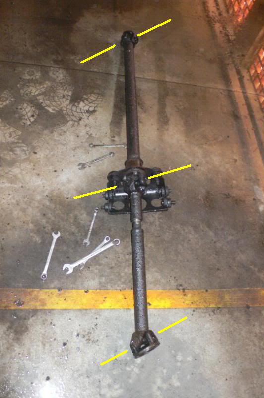 |
|
|
|
Post by djm16 on Jul 6, 2020 8:24:17 GMT
"when you have two properly phased and aligned joints on the same shaft, they cancel out"
Problem is of course that you have three, not two, joints on the compound shaft. To get perfect cancellation of the elliptical component in the UJs, one of the three joints has to be set at a zero degrees to perpendicular to its flange (as in Enigmas first post / diagram).
Re the softness of the centre mount, I absolutely take Enigma's point about solidifying it so that it becomes effectively the gearbox output flange extended, and I would not discourage you from trying it ...
However, consider the way a spin drier is mounted in very soft springs. This is to keep the resonant frequency of an unbalanced drum at a very low value. The drum spins up through the resonance and then self-balances with minimal vibration unless the load is very off-centre. Stiffening up the spring mounts would shift the resonant frequency up into a range where more energy is stored in the higher frequency vibration.
|
|
|
|
Post by johnwp5bcoupe on Jul 6, 2020 9:10:05 GMT
Jens...can you physically move the centre coupling up/down or sideways in its centre mount? An answer of either Yes or No will tell you whether the issue is there or else where in the system. Consider the first half of the tailshaft up to the centre coupling as a straight line or extension with the crankshaft axis. Don't think of it as part of the tailshaft...think of it as the rear transmission flange/coupling. Would you fit a jelly like mount at the rear of the transmission? As for the first half of the tailshaft running dead straight and 'supposedly' wearing the universal joint rollers out prematurely...it really ain't gonna happen in a day or two! Nothing in a transmission assembly is mounted that rigidly or metal to metal. It all moves about to a degree under general driving conditions. * It's interesting to note that once the drive shaft issue was brought to light it opened up something of a pandora's box with regard to other P5 owners also have similar experiences with their cars. Vince what about Rose Joint's in place of the rubbers? a step too rigid? |
|
|
|
Post by enigmas on Jul 6, 2020 9:59:42 GMT
Hi John...IMHO I believe there has to be a small tolerance/allowance for movement. Most of the centre CV (constant velocity) joints in modern split tail shafts I've investigated are all mounted in solid rubber doughnut mounts. The 'doughnuts' are vulcanized to a steel mount/brace which then bolts directly to the car's transmission tunnel. I'm sure I have a Holden Commodore split shaft like this tucked away under my house. On my P5 coupe I also fitted a diagonal cross-brace to the rear transmission mount to limit any side to side play. Once again utilizing lower shocker mounts and 2 conical bushes in the manner of a rose joint fitting. Same principal but not as rigid. I'm sure a simple limiting brace could be attached to the P5 centre mount utilizing the bushes available for the front sway bar. These bushes are a universal fit for most sway bars, are cheap and available in rubber or urethane. Utilizing a long threaded rod with suitable nuts & washers would easily provide a simple brace to limit and control errant movement. Fit it where that ridiculous light spring sits/attaches. It would be definitely worth trying. (A rubber bobbin mount....these have a stud protruding from either end...might be another easy/viable option)   PS. The diagonal trans mount on my coupe that I referred to earlier can be seen in the picture below. Instead of rubber I used red nolathane bushes 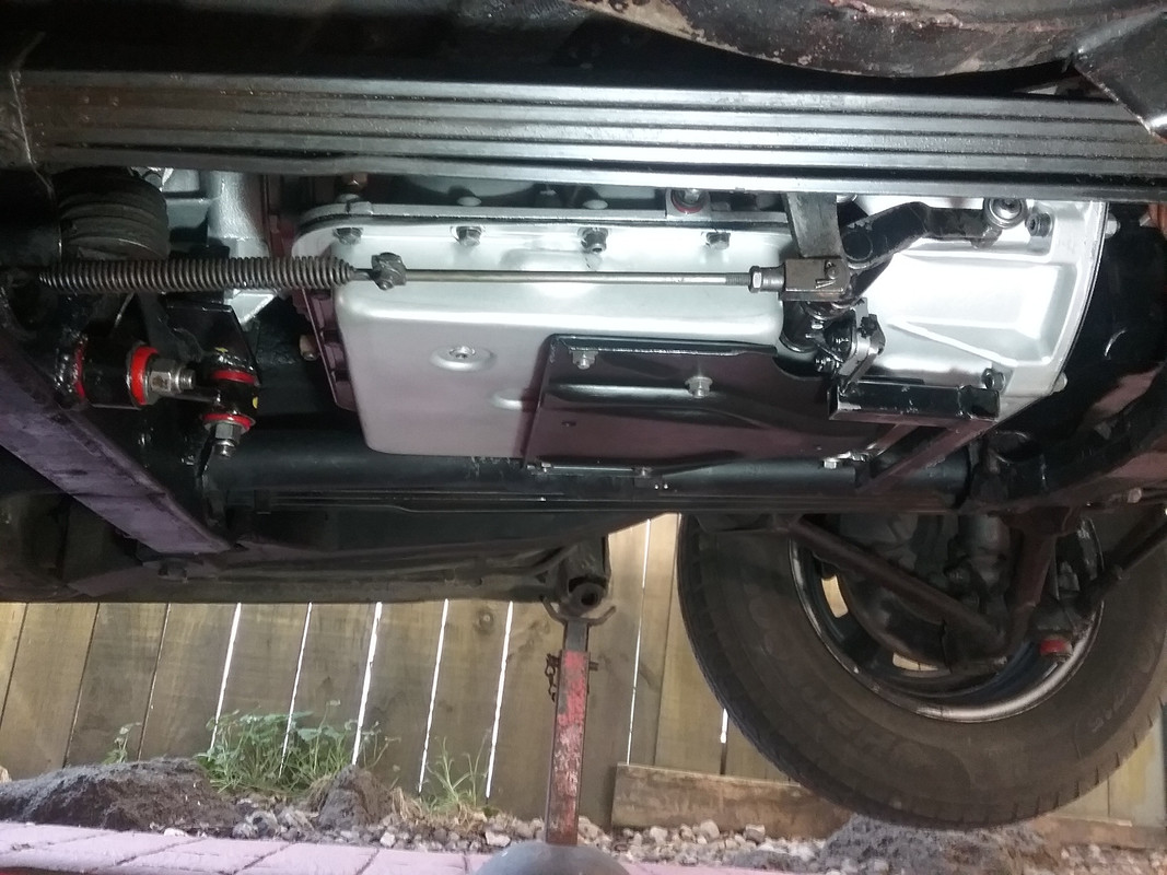 |
|


