|
|
Post by enigmas on May 28, 2021 0:31:39 GMT
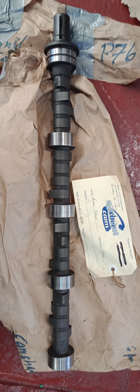
I've had a spare P76 engine aside for years. Over time I've had various pieces machined and fettled to either restore or refurbish what was required. The crankshaft has been reground and polished, there's a reground camshaft along with a fresh set of lifters, the heads have been professionally rebuilt and fitted with modern hat seals, rods and pistons have been weight matched, the rotating assembly has been rebalanced and the ZF transmission coupler remachined as the rear crankshaft flange wasn't within spec and created a .015" runout once all the driveplate and related pieces were stacked-up. The hybrid manifold (P76 inlet manifold & twin zenith stromberg CD carbs) I've been cobbling up on the side will be fitted to this engine. The complete assembly will be fitted into a purpose built engine stand to initially run the engine. That's the plan. I aim to update this blog as I proceed. So if interested, stay tuned.  |
|
|
|
Post by enigmas on Jun 1, 2021 9:14:37 GMT
I've got all the pieces to assemble the engine at hand but have managed to put myself out of action for a couple of days by straining my back whilst doing some basic maintenance on my coupe's exhaust system, rear springs and differential breather. So as consolation, here's a little video and sound file of the car idling in my driveway.  |
|
|
|
Post by Mike’S-a-loon on Jun 1, 2021 13:41:23 GMT
Two exhausts! Boy racer...  |
|
|
|
Post by enigmas on Jun 1, 2021 23:19:13 GMT
No...those days are well and truly past Mike. I simply like symmetry. |
|
|
|
Post by enigmas on Jun 2, 2021 10:52:16 GMT
|
|
|
|
Post by enigmas on Jun 3, 2021 11:15:41 GMT
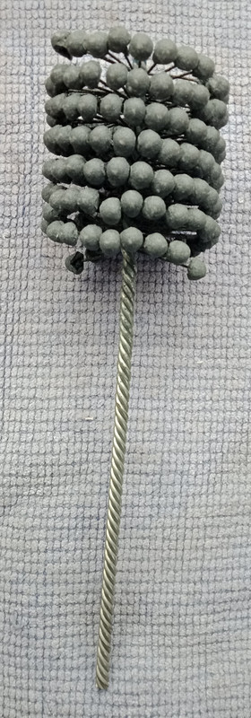
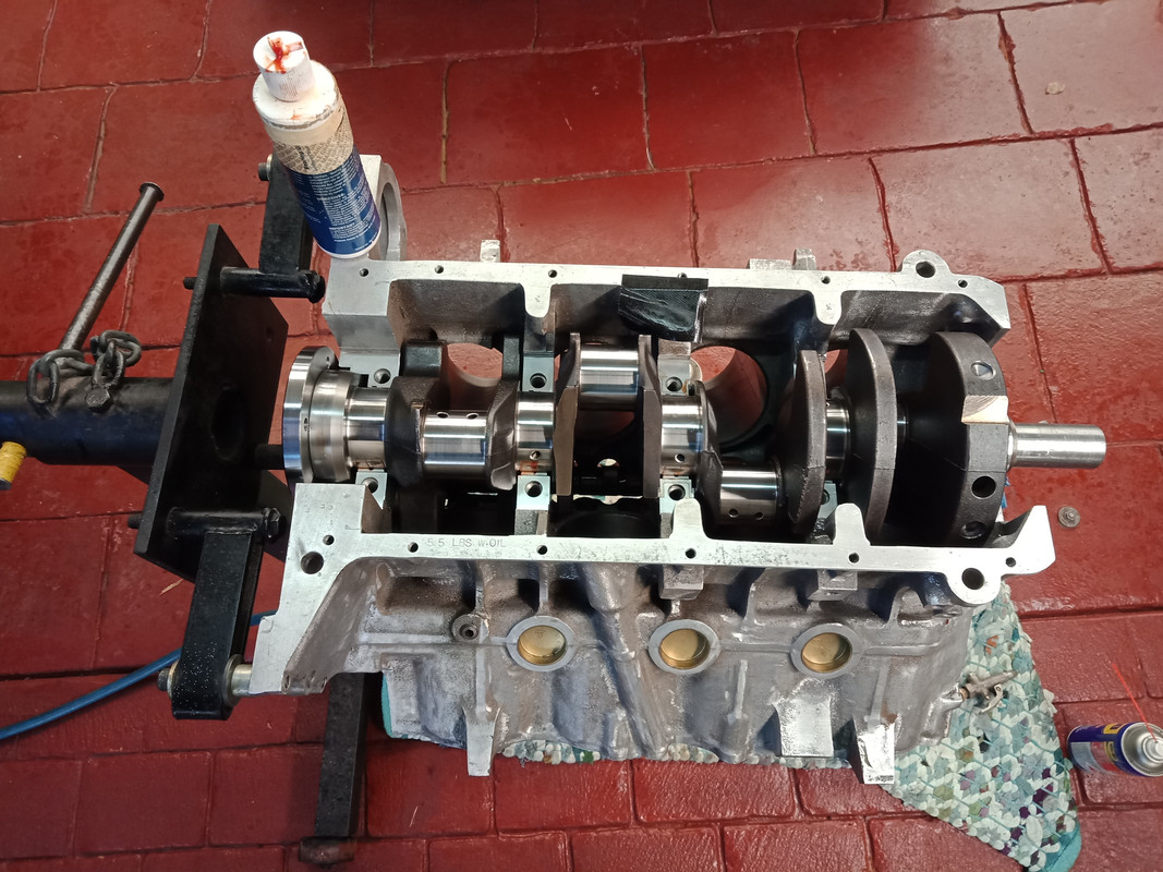
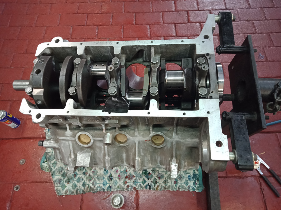
A little Update.There's one good thing, just thinking off hand, about classic car engines built in the UK and that is, gudgeon pin locks. There's either a clamping bolt on the little end of the conrod or there's circlips, spiral locks or something just as readily removeable. Unfortunately GM and most manufacturer's of 1950s, 60s and 70s V8 engines in the USA saved some money by virtue of the method used to lock a gudgeon pin on a conrod. Yes, it's the marvellous interference fit method. Heat the conrod little end till it's blue hot and allow yourself about 10 fun filled seconds before the conrod little end places a vice like grip on the gudgeon pin. That's 10 tense seconds fitting the conrod to the piston whilst also trying to centre both the pin and conrod little end in the piston at the same time. I conveniently put thoughts of fitting conrods to pistons on GM V8s way into the dark recesses of my brain until next time arrives. Fortunately I also have a press so I can rectify an off centre pin but this process of adjustment can also be nerve wracking. I did fabricate a basic jig to ease the process but you still have to be focused and quick. I could have done with some encouragement from Yoda! 😉👍 After a day toying with pin fitting I had time to fit 4 pistons and rods to the engine. Here are a few pix. Conrods and pistons laid out noting their weights and partners.  Conrods and pistons mated. Note the yellow dot to dot method. Get this wrong and you're in a world of pain! 😣  There is an overall weight variation of 5 grams. It's illustrated by the image below (equivalent to one thin oil expander retainer ring.  Fitting pistons and rods to the engine. My 36 year old piston ring compressor has seen better days. It great fun when the ratchet lock decides to release with only 2 of 3 rings fitted into the cylinder. The ring compressor can be just seen to the right of the yellow handled hammer on the rug at the base of the image. 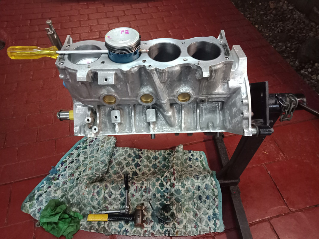
|
|
|
|
Post by enigmas on Jun 4, 2021 10:12:29 GMT
A Brief Update. Today I finished fitting the remainder of the pistons and rods and torqued down all the big end caps. Spent a couple hours cleaning bits and pieces so that I can button up the bottom end tomorrow. As an aside Victoria is under covid lockdown again with a 10km travel radius from home if you live in the metro area, as I do. So there's plenty of time (whilst isolated) to focus on this project. If anyone is wondering about the colour coding (paint pens)...well it keeps me focused and is also a visual reminder of either what I've done or what I am doing. Here's a few pix.  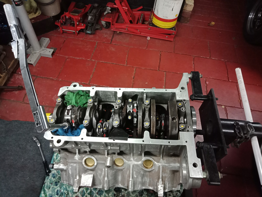  I've had this Warren & Brown tension wrench since I was 16. It's definitely a family heirloom. 
|
|
|
|
Post by Mike’S-a-loon on Jun 4, 2021 12:44:51 GMT
Hey Vince,
Sorry about the lockdowns. I'm currently stranded in NZ, my 4 week trip here from Taiwan has become 10 weeks... I had flights to Melbourne for a 2 week side trip early next week, but guess what? Dang. I won't get to see my Rover for probably another year... stay safe mate and use your time well. That 10k limit will be appreciated next time you fill up on LPG, at least you won't be using much!
|
|
|
|
Post by enigmas on Jun 5, 2021 0:14:51 GMT
You obviously do a bit of globe trotting Mike...just wondering where you reside for most of the time when you're not working? ~ Cheers |
|
|
|
Post by Mike’S-a-loon on Jun 5, 2021 2:55:00 GMT
Taiwan! I've lived there for 6 years, expat for a big American company. Melbourne is home, but I'm a Kiwi originally. I left Taiwan to come to Auckland to look after my old Mum post cancer surgery, then suddenly Taiwan had its first major covid outbreak (they were doing so well), and lockdown started, flights got cancelled, and here I am still! The side trip to Melbourne was a good idea when I booked it...
|
|
|
|
Post by enigmas on Jun 6, 2021 12:14:59 GMT
Lookin' for Stuff & Checking out the Oil Pump.
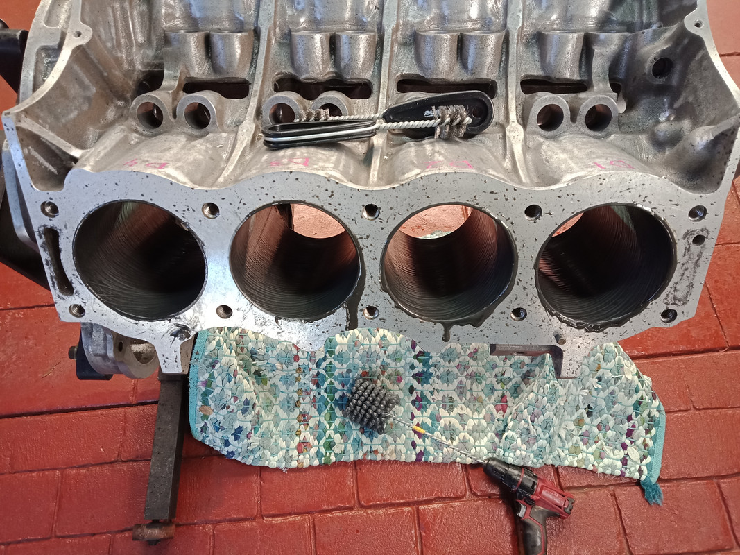
There's nothing like walking around in circles. Spent a good portion of the afternoon hunting down a couple of gasket sets that I'd managed to file away in a safe place somewhere in my garage/studio space. An hour or so later I finally found them in plain sight on top of a plastic storage tub but under some fresh shop rags I'd placed there several weeks ago! Having found the gaskets I could now move my focus to cleaning the timing cover, the waterpump and also checking the oil pump components, including the face of the bottom plate of the oil pump. This is often scored especially if the clearances haven't been properly considered. See pic below. The oil pump base can be restored by facing it on a flat plate with emory paper or similar. Once this is done it's advisable to check whether the gears are sitting proud of the housing and to make an allowance for this. The gasket thickness should be checked with a set of verniers and an allowance for crush included. Once assembled in the timing case it's worth rotating the drive spindle with a screw driver to ensure the pump gears aren't binding on the end plate. The last thing you want to occur is to have the pump gears shred aluminium shavings into the oil galleries through to the bearings. Check the pressure relief valve to ensure that its not sticking, then tbe bypass valve and the jobs done. Here are a few pix of the oil pump being checked and fettled. Checking the end clearance of the gears. These are at .003".  Facing/smoothing the bottom face of the pump gears.  One of two dismantled pump base plates. Note the entrained dirt and grit. 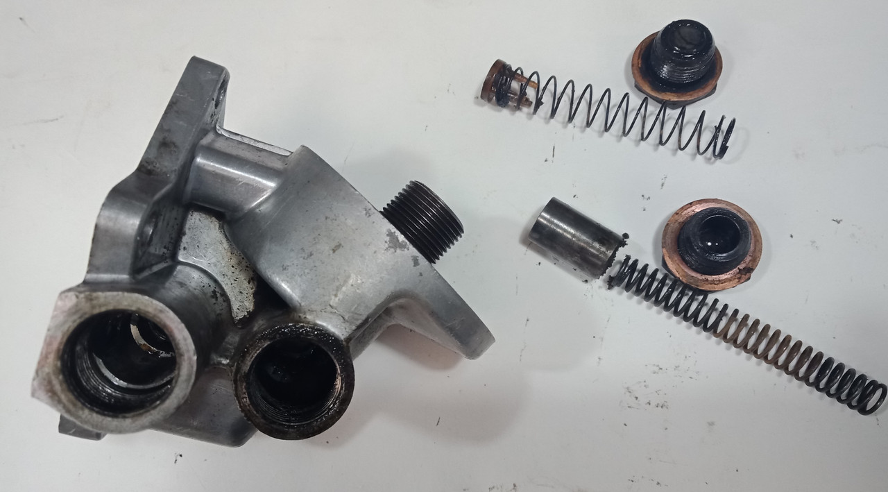 Note the deep scoring on this base plate.  Here are both base plates. I'll be using the one on the left after facing it. Note the slight differences in the machined faces of the base plates.  Here are the 2 valves within the oil pump after they've been thoroughly cleaned. The relief valve on the left and bypass to the right. The copper washers were lightly surfaced on a disc sander then annealed for reuse.  One of the last things I did before reassembling the pump was to measure the baseplate gasket. I had several over from remainder gasket kits and they do vary slightly. The ones I had measured at .009" and .014". As the pump gears are .003" above the face I chose to use the thinner of the 2 gaskets. This should yield about .006" clearance from the base plate. 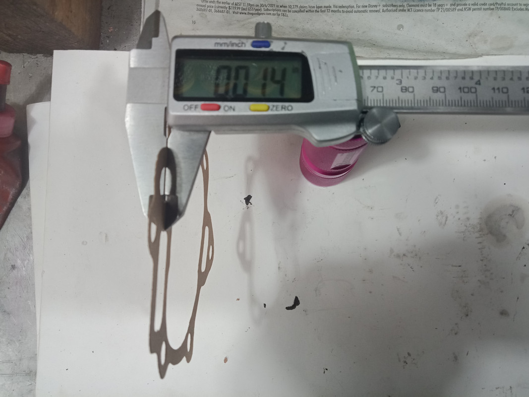 
|
|
|
|
Post by enigmas on Jun 7, 2021 3:15:05 GMT
Checking Timing Chain Set Viability. I have a whole series of WSMs that relate to either the 3.5 litre Rover V8s or the Leyland P76 4.4 litre V8 engines. I've collected these over years so there's quite an extensive library of info that I can access to cross reference specific tasks. Usually there's a piece of tech info that relates to a particular task/procedure that's not covered in the other WSMs. So this is what I found. Generally if you open an engine it's to do something major. If its never been touched before most of the components will require careful assessment, restoring/machining and/or replacement. And so it generally is with the Timing Chain Set. Here's a couple of checks that can easily be carried out on a timing chain set if for whatever reason you've had to remove the timing cover. Procedure 1. The procedure below is taken from a P76 V8 WSM. Note: .1875" is virtually 3/16" Imperial.  The images below identify the method.  Hold the crankshaft stationary as shown (if required.) Rotate the camshaft sprocket clockwise then counter clockwise to tension the chain and then to release chain tension. Movement of the marked dot on the chain taken in relation to the fixed mark on the tape indicates wear/stretch. The chain shown indicated movement of 1/16" According to the WSM spec this chain set is still viable. Replace the set if movement indicates at 3/16".  Procedure 2. (Engine in car. No dismantling required) Turn the engine to TDC number 1 cyl firing. Align the TDC timing marks on the pulley and pointer precisely. Remove the distributor cap. Observe the rotor button. You may need an assistant. The spark plugs should also be removed to ease the following. Rotate the engine 7° in a clockwise direction. Whilst doing this, note when the rotor button starts to first move. Now rotate the engine in a counter clockwise direction. (This will also take up any slack in the chain) Assessment. If the rotor button only starts to rotate/move at the 7° point the timing set is well worn and requires replacement. Note. A worn set affects both the valve timing and the ignition timing as the distributor is driven off the camshaft gear. AddendumAnother little update to the above. Fixing a wire pointer to the valley cover end bolt as shown below, will also yield valuable info with regard to the condition of the Timing Chain Set. Note the 2 images below. The 1st illustrates alignment. The 2nd image illustrates movement of the camshaft gear...showing approx 1mm or the thickness of the wire used.  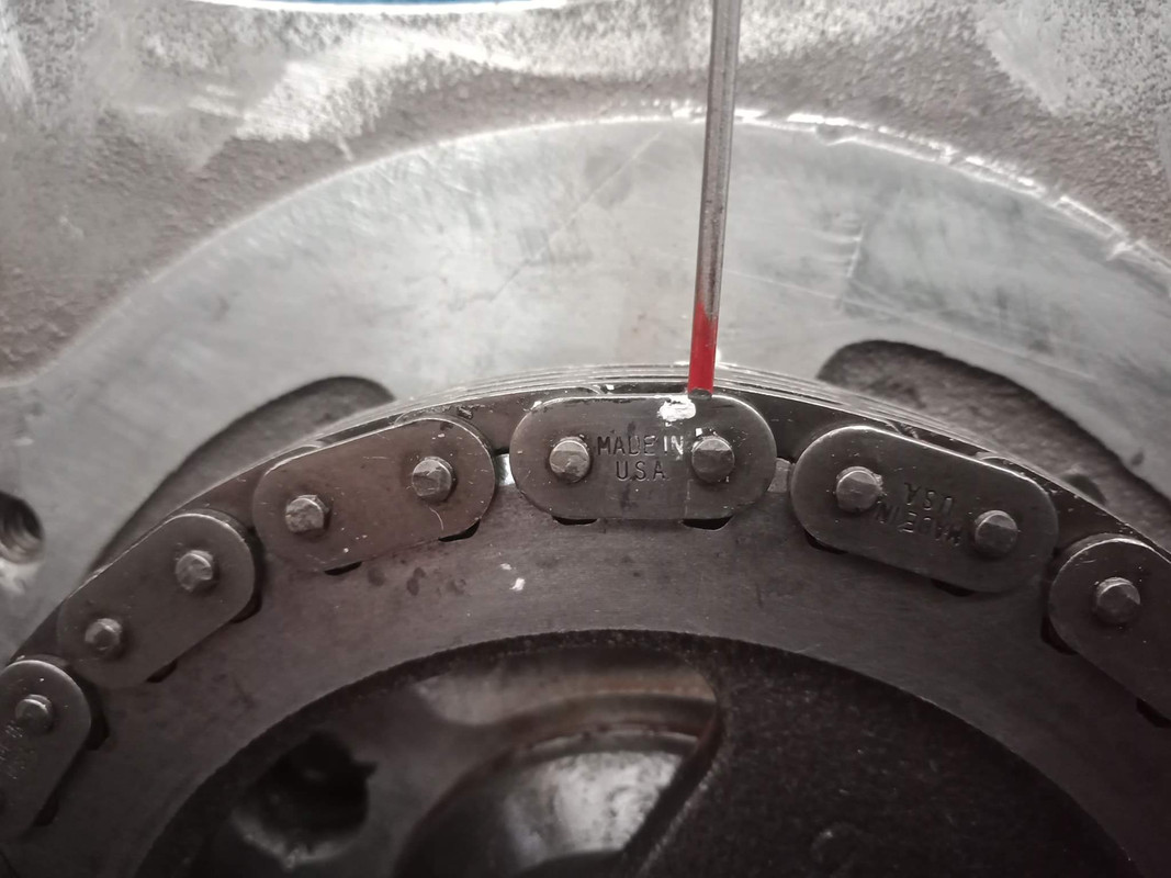
|
|
|
|
Post by enigmas on Jun 7, 2021 23:09:30 GMT
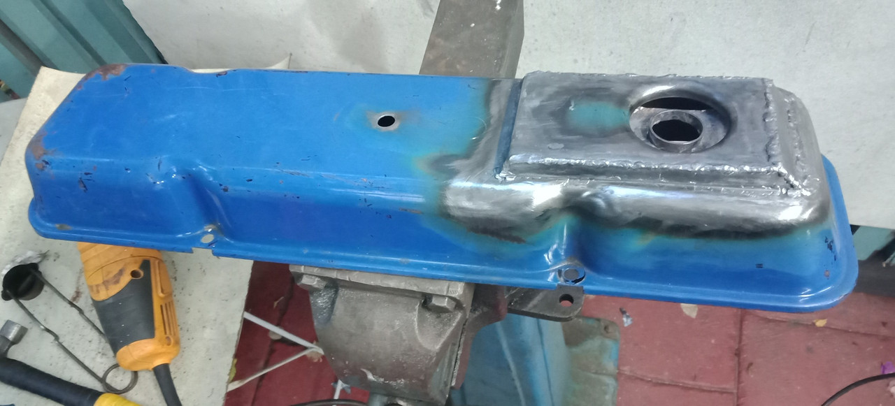
Beatin' on the SumpGiven the age of these engines and their Rover 3.5 litre cousins most have had quite a long period of service and most likely have also had numerous mechanics attend them in some manner or another. If your particular car is marking it's spot consistently, then perhaps a contributor may be a deformed sump flange. Take a close look at this sump resting on the sleeper especially the flange area. Note the huge gaps at the flange surface. 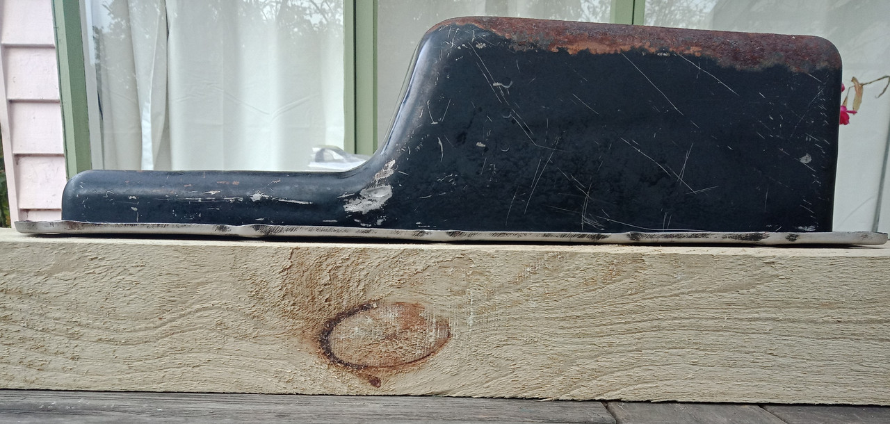 As the sump is a thin (18 gauge?) stamped mild steel item it's easily seen how it could become deformed through repeated hamfisted tightening sequences 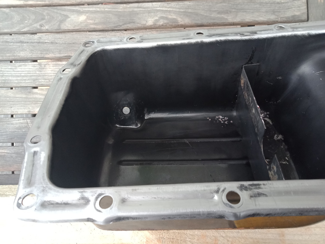 This image is merely a trial fitting to check the sump flange fitting clearance on the engine. No gasket is fitted. 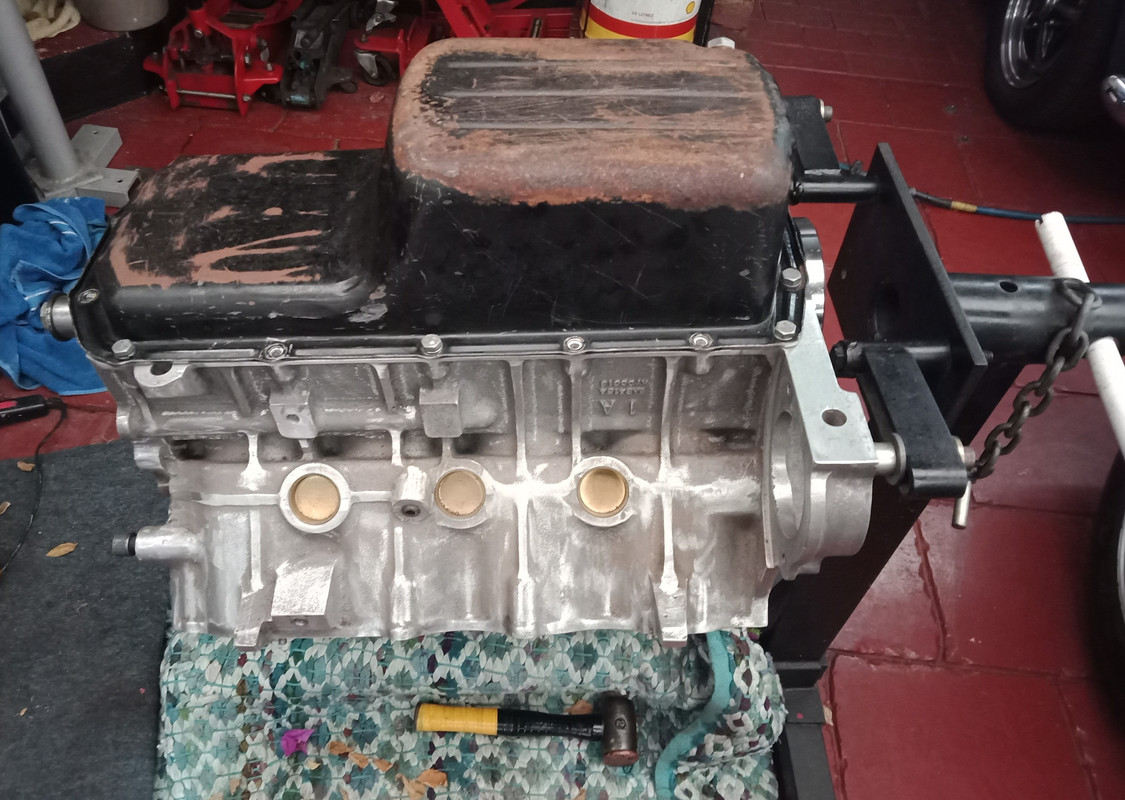
|
|
|
|
Post by enigmas on Jun 8, 2021 11:06:41 GMT
Prepping Cleaning & Painting stuff. Just a little update. Winter is beginning to set in and it's chilly outside. Spent 3 - 4 hrs cleaning and prepping parts for paint. As it's not an ideal temperature outside for painting I use a hair dryer to both warm the pieces and aid in flash drying the items as I'm painting them. All the paints I use are solvent based so they flash dry quite fast. Any bare metal or alloy pieces are etch primed prior to a final colour coat. Here are the pieces. The sump cleaned up and ready for primer.  This is the colour coat, an aluminium toned engine paint. 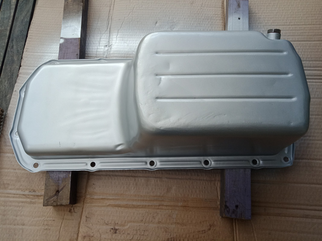 Both the timing cover and waterpump in etch primer. Colour coat yet to be applied.  The 2 items above will be painted tomorrow but not permanently affixed to the engine as I'm waiting on some parts to arrive before buttoning it up.
|
|
|
|
Post by enigmas on Jun 9, 2021 10:14:08 GMT
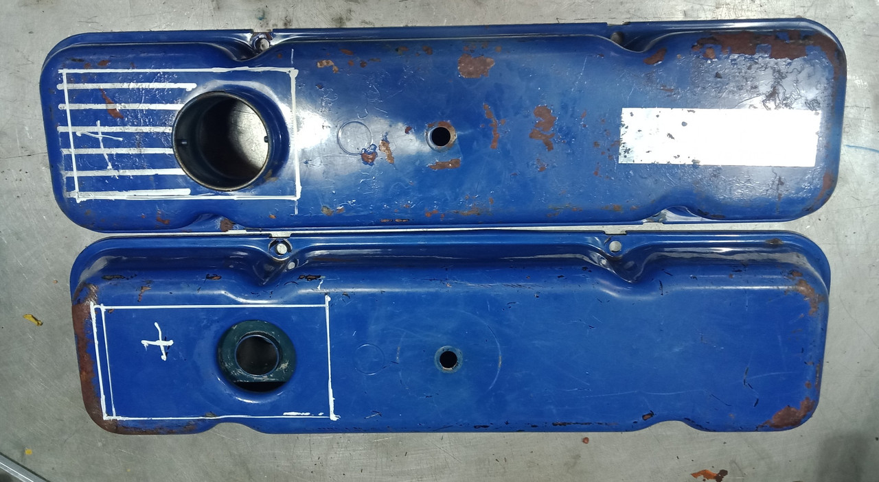
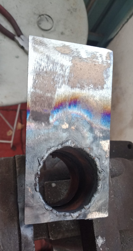
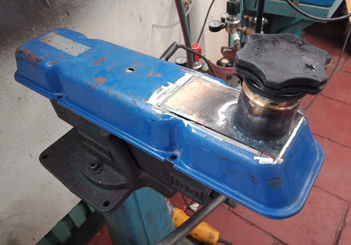
Painting Stuff_Take 2We had a bit of deluge in beautiful downtown Bentleigh today. Spent a good portion of it inside due to the rain but managed to get a bit of prep and paint onto the following few items when it abated. Certain parts for P76 V8s are getting very difficult to locate. One these items is the stamped tin valley cover. Any existing spares have seemingly dried up, so the only option available is to reuse an existing item. NB. If wondering how the valley cover will effectively seal between the cyl head intake and coolant passages and the inlet manifold flange, I use a Loctite anerobic sealant for this task, not silicone. www.henkel-adhesives.com/au/en/product/flexible-sealants/loctite_518.htmlThe images below outline today's task. Cleaning like this on both sides took about 45 mins. 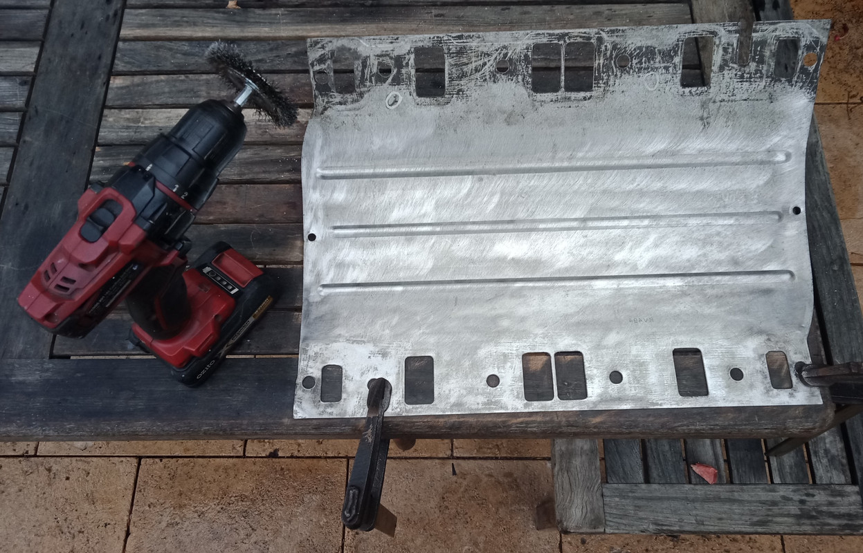 It was then wiped over with solvent and one side masked off. 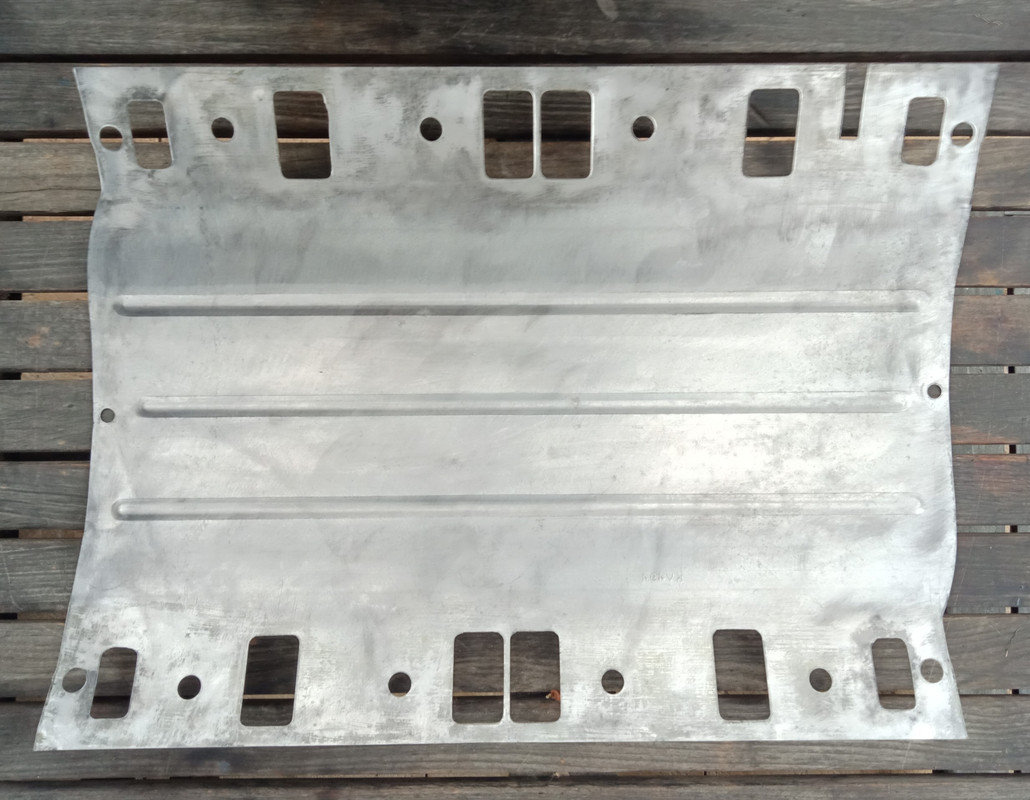 The cover was etch primed and finally painted with high temp/fuel resistant engine paint. ![]()  This side faces the engine valley and still retains it's galvanised finish so was left unpainted. 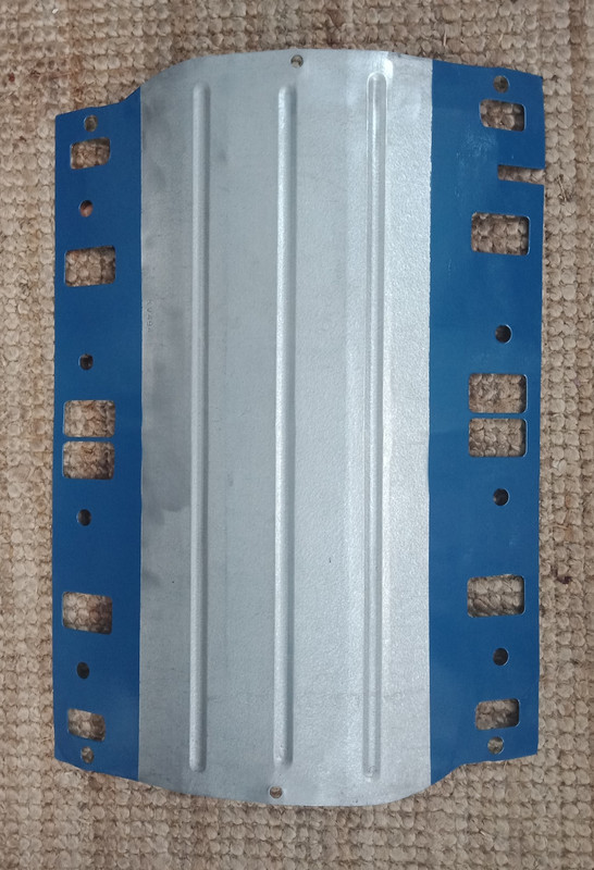 As both the waterpump and the timing cover were previously etch primed, they only required masking in specific areas before both were coated with the same colour engine paint. 
|
|
|
|
Post by enigmas on Jun 10, 2021 10:19:01 GMT
This is not really an update, as I'm waiting on some pieces to arrive via snail mail before I can finish assembling the engine. Bolted the waterpump to the timing cover, knocked in the new front seal (it's slightly larger in diameter than the Rover item) and loosely bolted the cover to the engine, moreso to protect it from any detritus getting into the block. 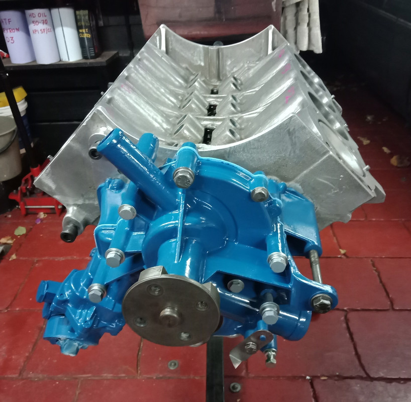 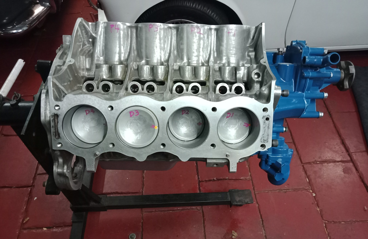 |
|
|
|
Post by enigmas on Jun 13, 2021 10:13:45 GMT
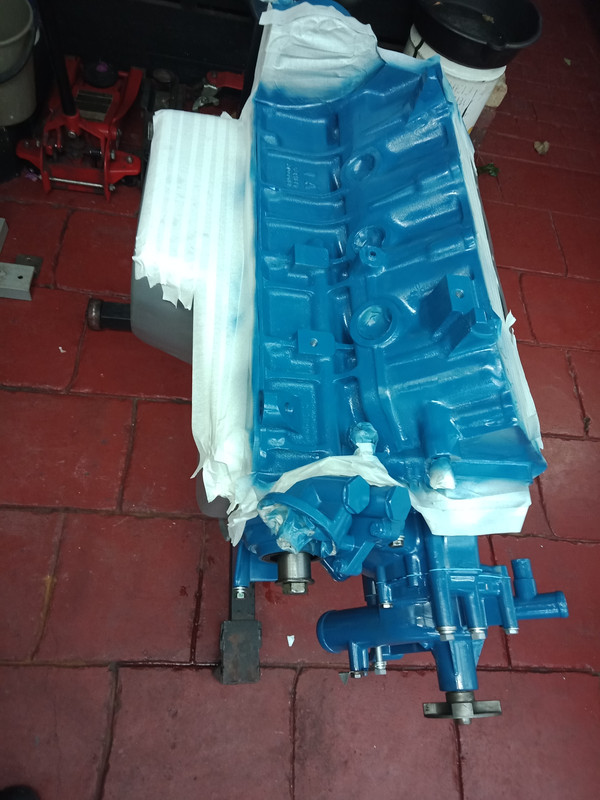
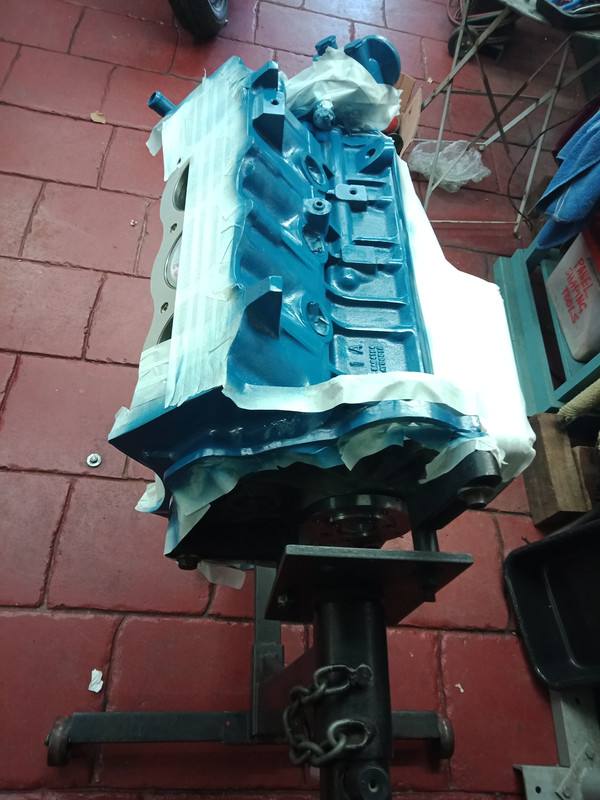
A perfect example of how not to paint an engine!   |
|
|
|
Post by enigmas on Jun 13, 2021 10:24:24 GMT
|
|
joffa
Rover Rookie

Posts: 82 
|
Post by joffa on Jun 13, 2021 13:38:53 GMT
Great post and love seeing the differences between the P76 V8 and the Rover 3.5. Good thing they had they modern rear main oil seal and you don't have to deal with the rope seals and all that entails.
Also, how'd you think they paint will go on the water pump area of the front timing cover? I have always been hesitant to paint in there as I never knew if the paint would stay there or peel off. The blue paint for the blocks great.
|
|
|
|
Post by enigmas on Jun 13, 2021 14:12:21 GMT
Hi Joffa, there's no issues with the paint staying in place if the engine or component is properly prepped for it. This P76 V8 is currently in my P5 MK3 coupe and has been for a number of years since receiving a cosmetic freshen up.  and this combo (MG red engine paint) is in my ZB Magnette. 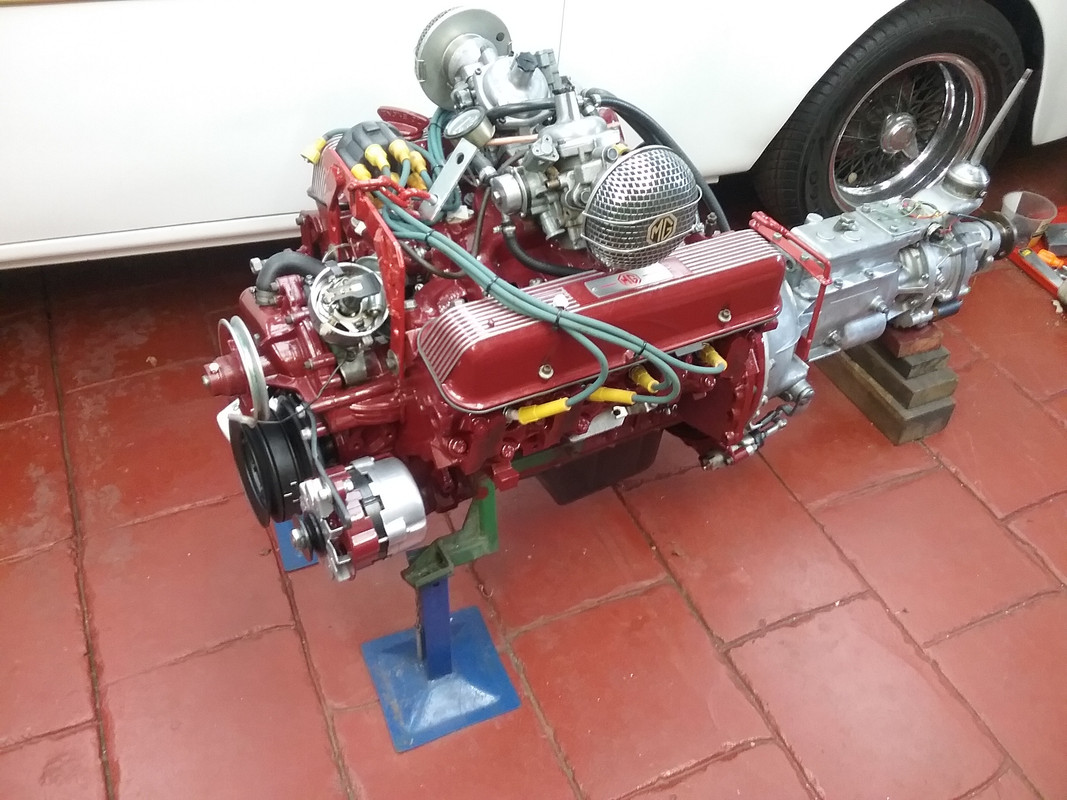 Just ensure that you thoroughly clean the items that you're going to paint and then use properly formulated engine paint...not any old aerosol you may have to hand. And of course, follow any instructions for applying the paint to the letter. I initially start with a light coat of etch primer as a base. NB. In cold weather use a hair dryer to warm the surface of the part and also to assist solvent evaporation. |
|
joffa
Rover Rookie
Posts: 82
|
Post by joffa on Jun 13, 2021 14:26:49 GMT
Yep good tips and nice to know the paint has stayed there for your engines. I had mine sand blasted a while ago that removed the grey anodized looking finish which I wasn't happy about but have been wondering if I should paint it or not. I'll have a think but yes I have lots of proper engine paint around so may give it a coat.
|
|
|
|
Post by enigmas on Jun 13, 2021 22:31:42 GMT
|
|
|
|
Post by enigmas on Jun 16, 2021 12:26:53 GMT
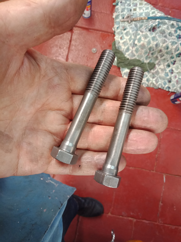
Moving Forward_Miscellaneous TasksThese included: * Painting the front of the engine block * Installing the new Timing Chain set, * Fitting the timing cover permanently, * Fitting the sump permanently, * Fitting a new set of hydraulic lifters * Repairing a suspect thread with an insert * Fitting the DS cylinder head and torquing it down. The following pix including some with brief text outlines the tasks involved.  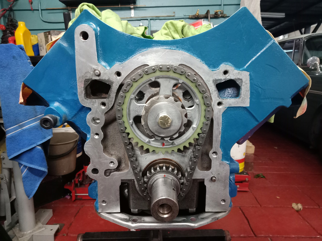 The red stuff is loctite (anaerobic) flange sealant. I like to use this as well as a gasket as it effectively fills small voids/imperfections in the case and block sealing surfaces. The timing case is a critical component because it is used to transfer both coolant and engine oil under pressure to the block. The sealant doesn't ball like silastic or clog oil galleries.  The timing cover permanently in place. Excess sealant can simply be wiped away.  Fitting the sump gasket (cork). The gasket was held to the engine sump flange with grease. The actual sump flange was given a narrow bead of suitable silastic to permanently affix it to the pan. In this way I can easily remove the sump at later date when I transfer the engine to my coupe as it has a customized sump.  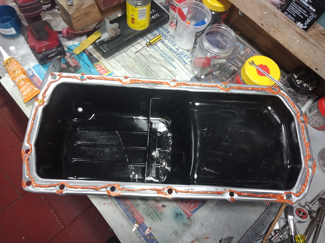 I torqued the sump bolts down to 40 inch lb (3.3 ft lb) as there was no torque specification given for these bolts. As it's a cork gasket I didn't want to overly compress or crush the gasket and cause it to fail.  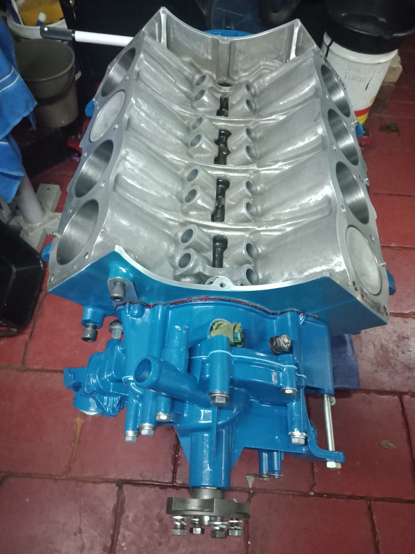 A new set of hydraulic lifters. Note the oil feed hole where the pushrod fits. The P76 uses this feed through the pushrods to oil the rocker gear. The Rover V8 feeds oil through the block to its rocker gear. A Rover cylinder head can be fitted to a P76 V8 by utlizing the P76 lifters and pushrods. This feeds oil through the pushrod and into the rocker cup of the Rover rocker gear.  Here's a page from the P76 V8 WSM that should prove useful to Rover V8 owner/restorers. A method for checking chain stretch. Although I purchased a new timing set the (steel) one that I had aside was still wholly viable illustrating negligible stretch or wear to the camshaft gear. 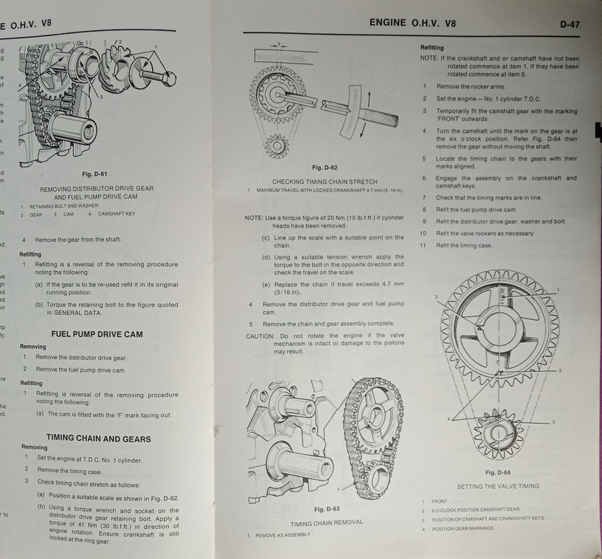 Masking and painting the cyl heads. 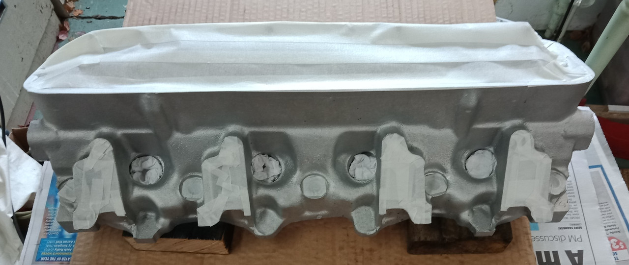 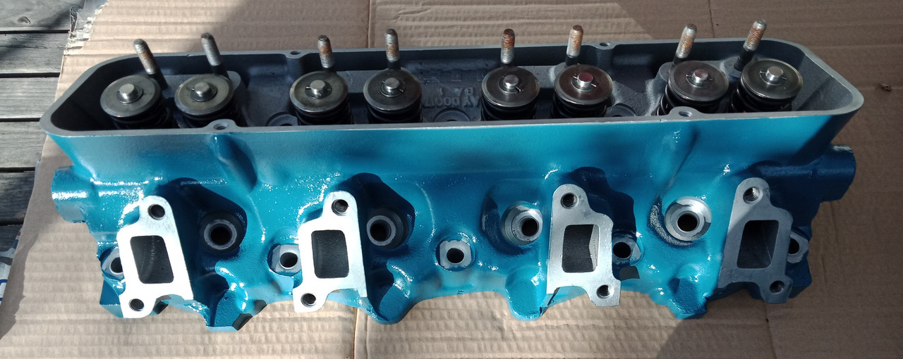 Repairing a suspect thread with a heli coil insert. 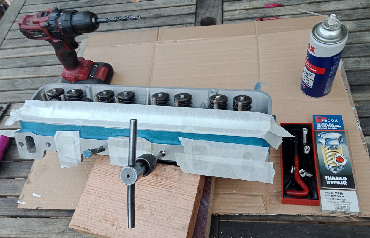  A relatively straight forward process. 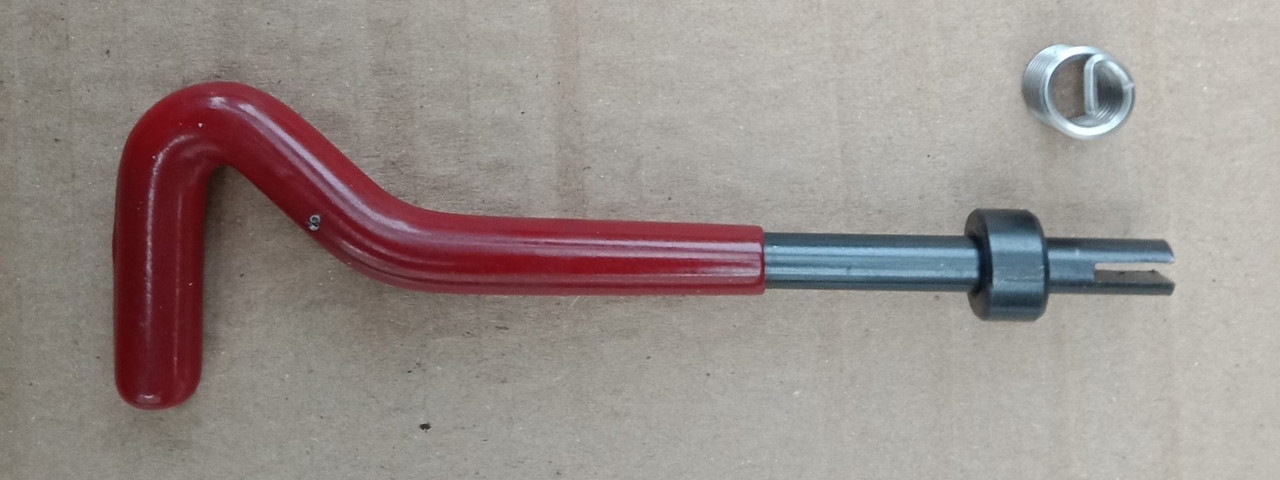 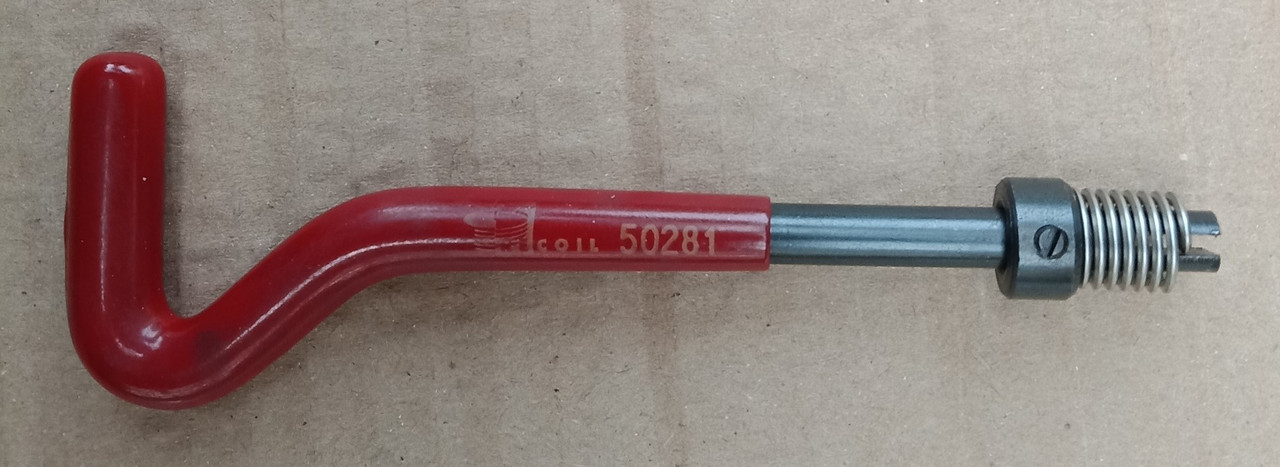 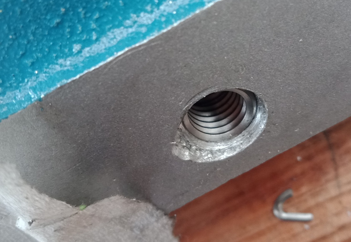 The engine block has been sitting around for a number of years so I always like to clean the critical threads by putting a tap through them. This generally cleans out any detritus within the thread. Fitting and torquing down the DS cyl head. I do this in increments of approx 15 ft lbs up to a set figure of 65 ft lbs. Torquing bolts to high tension on an alloy block is always a bit unnerving. Fortunately no issues on this side. I carefully clean and inspect the bolts, radius the lower sharp edges of the head on a disc sander so they don't bite into the washer and lightly surface the washers to ensure positive seating. I also use engine oil as a lubricant under the head and on the thread to limit friction and galling whilst tensioning the bolts. This process works for me. 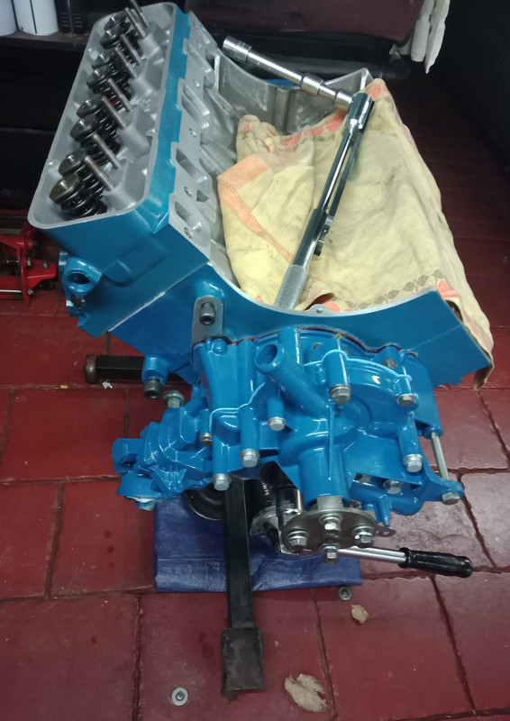 PS. Just incase any eagle eyes noticed...I used a 3/8" whitworth insert instead of a 3/8" UNC insert. The thread pitch on the former is 55° whilst the later is 60°. Yes they are different but very close, the bolts don't really notice any difference and thread in smoothly. Naughty but expedient as I had a set of inserts left over from a previous repair at hand.
|
|
|
|
Post by enigmas on Jun 21, 2021 15:03:27 GMT
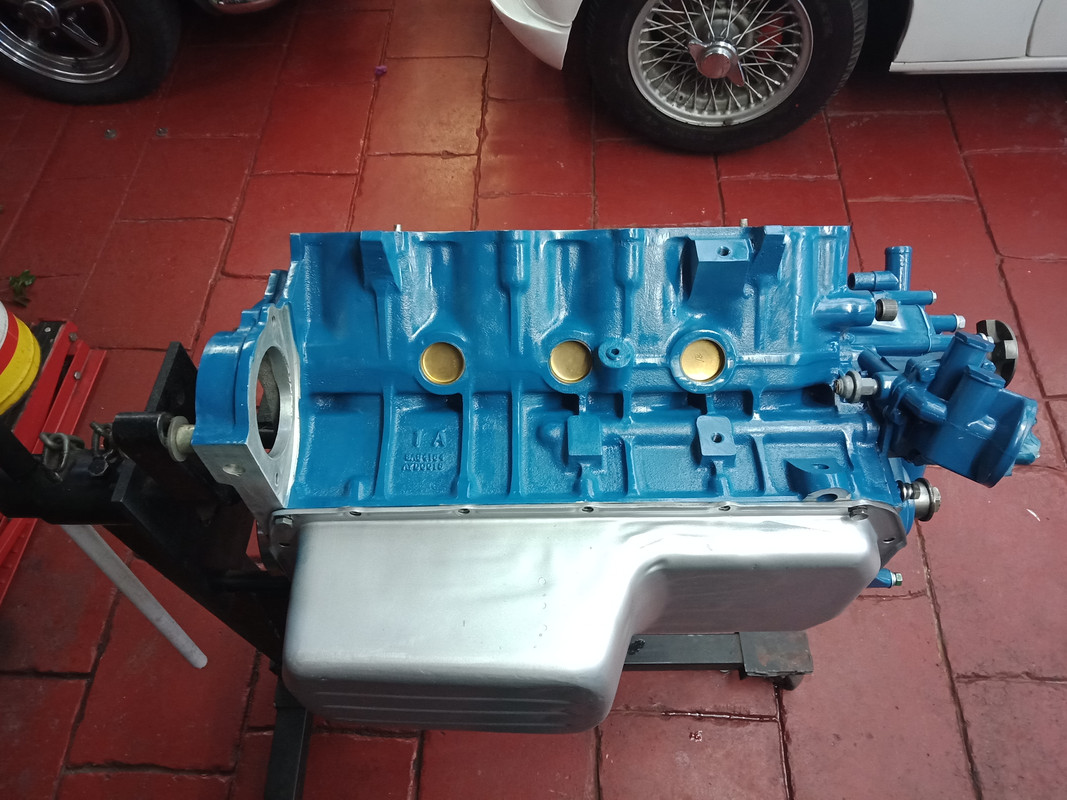
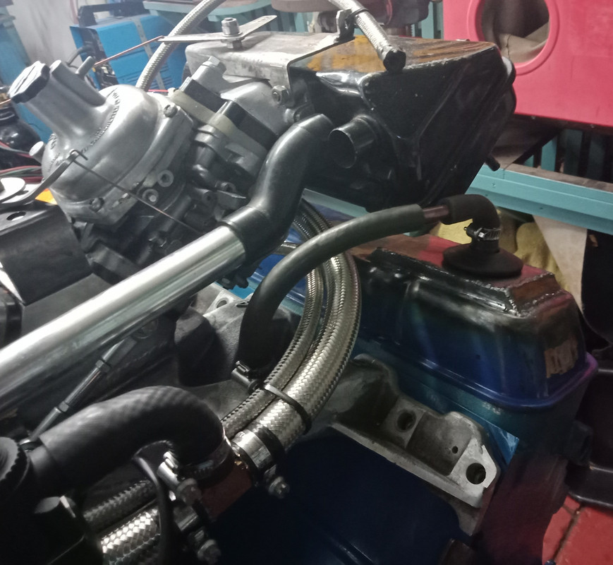
Doing other StuffI've had most of the bits pieces for this build stashed aside for years and I do generally try to be methodical and organised with the pieces by carefully bagging the parts. But given Murphy's Law in concert with a memory lapse as to where I placed a few pieces for safe keeping, it's inevitable that I'd need a few 'lost' bits. And so it was! A few head bolts, a pulley, a distributor hold down clamp, an alternator adjustment bracket, a set of P76 pressed tin rocker covers and most likely several other bits that I can't recall off hand. Anyway, after posting to a P76 forum one the guys said he could assist with the pieces I needed. Problem solved. He also preferred the barter system to cash. He had a whole stash of P76 waterpumps in varying condition and one new pump body. So we agreed on a deal, I'd assemble one good pump out of 3 bodies using a new old stock bearing he had aside. Here are a few pix. One of the pump bodies had a really corroded impeller...probably due to the owner using plain water rather than an appropriate coolant to protect the alloy from corrosion and electrolysis. 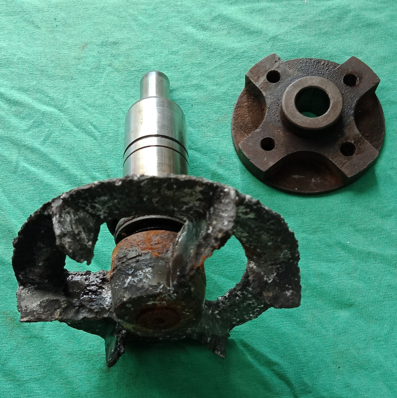  This is the NOS pump body and bearing. The 'good' impeller (shown) was removed from another pump and fitted with a new seal to the NOS pump body. 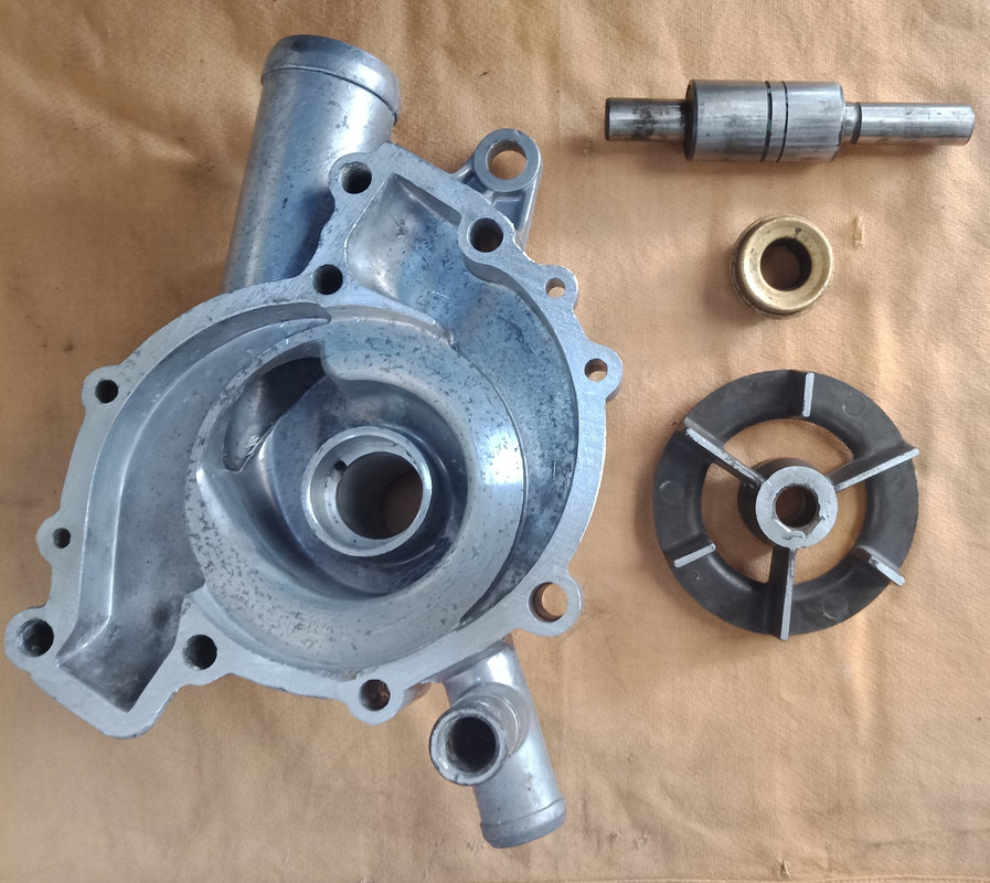 The impeller is a larger version of the P5B pump impeller. New seals can be sourced from Pool pump suppliers/repairers. ($25.00 AUD) The seals are identical to the original ones removed and are a direct fit in the Rover 3.5 V8 pumps. (P5B - SD1) Bearing and new seal fitted to the NOS pump housing. 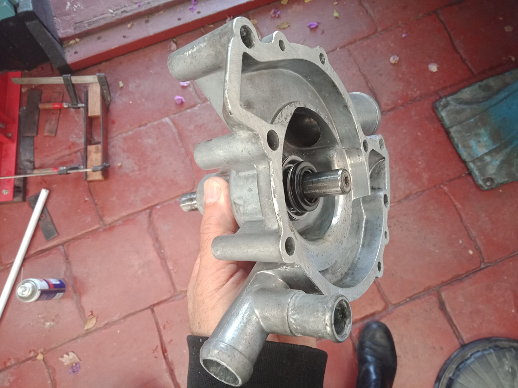 New seal ready to fit into the pump housing. 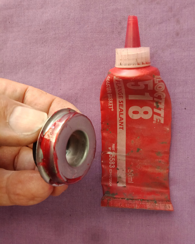 Seal in place 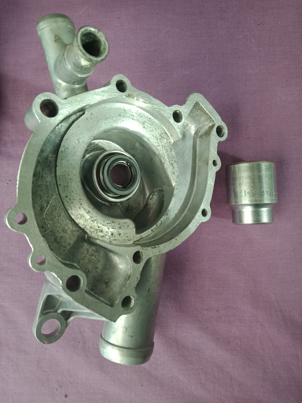 Impeller fitted. 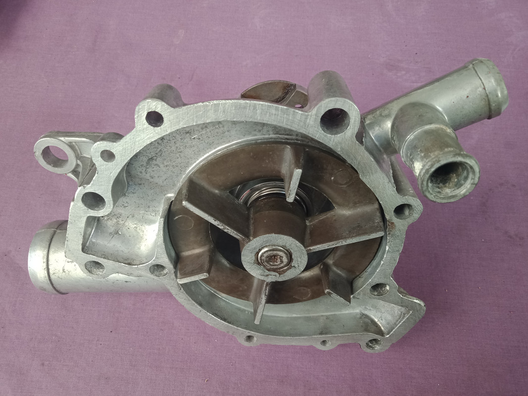 Pulley flange fitted.  Mocking-up the Engine Mocking-up the EngineAfter I'd finished refurbishing the P76 waterpump there was still some daylight left so I decided to mock-up the P76 engine. The PS cyl head was fitted temporarily with 2 head bolts, the valley cover similarly fitted and the inlet manifold in its complete state rested on top. I fitted a set of pressed tin P76 Rocker covers as they have a reduced height in relation to the Rover ones. The oil filler/breather cap (PS) will have to be moved forward if I decide to use them. The manifold, brackets, etc will all be cleaned and painted prior to final fitting. Here are the pix of the P76 V8 engine mock-up (front & rear views)  
|
|
|
|
Post by enigmas on Jun 26, 2021 2:34:13 GMT
|
|